
Understanding the 115V Pool Pump Circuit Architecture
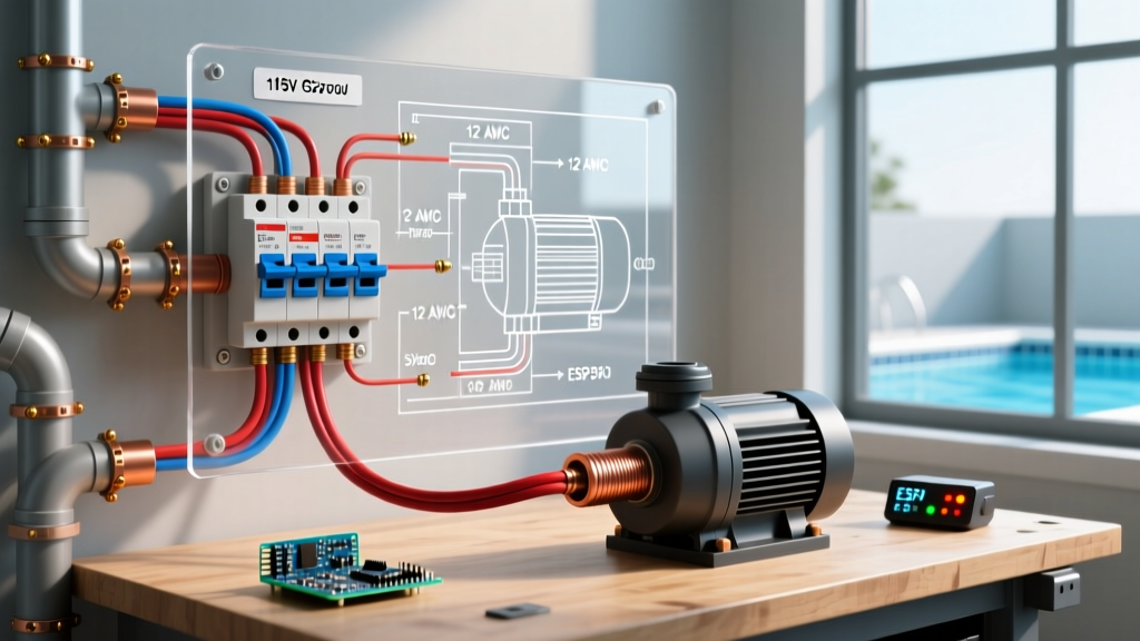
Wiring a single-phase, 115-volt pool pump requires strict adherence to the National Electrical Code (NEC), specifically Article 680, which governs swimming pools, fountains, and similar installations. Unlike standard household appliances, pool pumps operate in a high-moisture, high-risk environment where electrical faults can be fatal. When planning your electrical 115v pool pump wiring diagram, the circuit must originate from a dedicated GFCI-protected breaker in your main panel or subpanel, route through rigid or flexible non-metallic conduit, and terminate at the motor's terminal board with precise line, neutral, and ground connections.
NEC 2023/2026 Mandate: According to National Electrical Code (NEC) Article 680.21(C), all pool pump motors rated 115V or 230V must be protected by a Class A Ground-Fault Circuit Interrupter (GFCI). Standard thermal-magnetic breakers are no longer code-compliant for new pool pump installations.
Electrical 115V Pool Pump Wiring Diagram: Step-by-Step Flow
Below is the sequential pathway for a compliant 115V pool pump circuit, integrating the breaker panel, optional timer, and the pump motor itself.
Step 1: Panel Preparation & GFCI Breaker Selection
Most 115V pool pumps (typically 1 HP to 1.5 HP) draw between 10 and 16 amps under full load. You must install a dedicated 20-Amp GFCI breaker. For Square D Homeline panels, use the HOM120GFIC (approx. $48-$55). For Siemens load centers, use the Q120GFI (approx. $42-$50). Connect the black (line) wire to the breaker's load terminal, the white (neutral) wire to the breaker's neutral pigtail/load terminal, and ensure the breaker's coiled white pigtail is securely fastened to the panel's neutral bar. The ground bar must remain isolated from the neutral bar if this is a subpanel.
Step 2: Conduit Routing and Wire Pulling
Run Schedule 40 PVC conduit from the panel to the pool equipment pad. For the final transition from the rigid PVC to the pump motor, use Liquidtight Flexible Metal Conduit (LFMC) or non-metallic liquidtight to allow for vibration isolation. Pull three individual THWN-2 stranded wires: Black (Line), White (Neutral), and Green (Equipment Ground). Never use Romex (NM-B) cable outdoors or in wet locations, as it violates OSHA and NEC wet location wiring standards.
Step 3: Timer Integration (Optional but Recommended)
If integrating a mechanical timer like the Intermatic T101P3 (115V plastic enclosure, approx. $65), the black line wire from the breaker lands on Terminal 1. The black load wire to the pump lands on Terminal 2. The white neutral wires (from panel and to pump) are wire-nutted together and bypass the timer's switching mechanism. The green ground wires are bonded to the timer's ground screw and the equipment pad's grounding grid.
Step 4: Pump Terminal Board Configuration
Open the pump's rear wiring compartment. Critical Edge Case: Many dual-voltage pumps (e.g., Hayward Super Pump, Pentair WhisperFlo) ship from the factory set to 230V. Locate the internal voltage selector switch or the wiring schematic on the motor label and physically flip the switch to 115V. If left on 230V, a 115V supply will cause the motor to hum, fail to start, and eventually destroy the start capacitor. Connect the Black wire to Line 1 (L1), the White wire to Line 2 (L2/Neutral), and the Green wire to the Grounding (GRD) screw.
Breaker Sizing and Wire Gauge Matrix
Selecting the correct wire gauge is vital to prevent voltage drop, which can cause the motor to overheat and trip the breaker prematurely. The National Electrical Manufacturers Association (NEMA) recommends keeping voltage drop below 5% for motor circuits.
| Pump Horsepower | Max Load Amps (115V) | Required Breaker | Wire Gauge (Under 50 ft) | Wire Gauge (50-100 ft) |
|---|---|---|---|---|
| 0.75 HP | 11.0 A | 20A GFCI | 12 AWG THWN-2 | 10 AWG THWN-2 |
| 1.0 HP | 14.0 A | 20A GFCI | 12 AWG THWN-2 | 10 AWG THWN-2 |
| 1.5 HP | 16.5 A | 20A or 30A GFCI | 10 AWG THWN-2 | 8 AWG THWN-2 |
| 2.0 HP | 20.0+ A | 30A GFCI | 10 AWG THWN-2 | 8 AWG THWN-2 |
Equipotential Bonding vs. Grounding: A Crucial Distinction
A common failure in DIY pool wiring is confusing equipment grounding with equipotential bonding. They serve entirely different purposes.
- Equipment Grounding (The Green Wire): Provides a low-impedance path back to the panel to trip the breaker in the event of a short circuit.
- Equipotential Bonding (The Bare Copper Grid): Connects all metallic components (pool shell rebar, metal ladders, pump motor bonding lug, heater casing) together using a continuous 8 AWG solid copper wire. This does not carry current under normal conditions; it eliminates voltage gradients in the earth, preventing a swimmer from becoming the path of least resistance between two differently charged metal objects.
The 8 AWG bonding wire must be attached to the external bonding lug on the pool pump motor using a copper grounding clip. Do not confuse this lug with the internal threaded hole meant for the green equipment grounding wire.
Common Failure Modes and Troubleshooting
1. Nuisance GFCI Tripping
If your new GFCI breaker trips immediately or randomly, check for neutral-to-ground faults. In 115V circuits, if the white neutral wire accidentally touches the metal conduit or the equipment ground anywhere downstream of the GFCI breaker, the breaker will detect an imbalance and trip. Ensure the neutral is fully isolated from ground at the pump terminal board.
2. Start Capacitor Explosion
If the pump hums but the impeller does not spin, the start capacitor is under immense stress. This is usually caused by severe voltage drop (using 14 AWG wire on a 75-foot run) or leaving a dual-voltage motor set to 230V while supplying 115V. The capacitor will eventually vent or explode. Always verify the voltage selector switch and measure the voltage at the pump terminals with a multimeter while the motor is attempting to start; it should not drop below 109V.
3. Timer Motor Burnout
Using a 230V Intermatic timer (like the T104) on a 115V circuit will result in the timer's internal clock motor running at half-speed or burning out. Ensure you are using the 115V specific model (T101P3 or T101R).
Frequently Asked Questions
Can I use a standard 20A breaker and a GFCI outlet at the pump?
No. NEC Article 680.21(C) requires the GFCI protection to be an integral part of the branch circuit breaker or a dead-front GFCI device. Relying on a standard breaker paired with a GFCI receptacle at the equipment pad is a code violation for hardwired pool pumps and introduces unnecessary points of failure in wet environments.
Does the pool pump need to be on a dedicated circuit?
Yes. The Association of Pool & Spa Professionals (APSP) and the NEC mandate that pool pump motors must have a dedicated branch circuit. Sharing the circuit with pool lighting, outdoor receptacles, or landscape lighting can lead to overloaded neutrals and nuisance GFCI tripping.
What size conduit do I need for three 10 AWG THWN-2 wires?
According to NEC Chapter 9, Table 1, conduit fill for three or more wires is limited to 40%. Three 10 AWG THWN-2 wires easily fit inside a 1/2-inch Schedule 40 PVC conduit. However, most professionals use 3/4-inch PVC to make future wire pulling easier and to allow for heat dissipation.