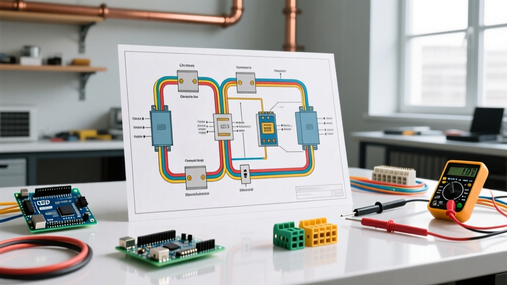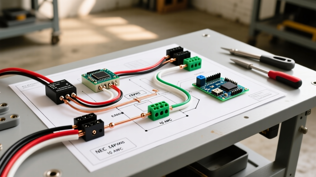

Decoding the Standard 240V Electric Oven Wiring Diagram
Wiring a modern electric range or built-in wall oven requires a precise understanding of 240-volt circuit architecture. Unlike standard 120V receptacles, an electric oven wiring diagram integrates two hot legs, a dedicated neutral for 120V control boards and interior lighting, and an isolated equipment grounding conductor. Under current National Electrical Code (NEC) standards, the legacy 3-wire setup (which improperly bonded the neutral and ground at the appliance) is strictly prohibited for new installations. Today, the 4-wire NEMA 14-50 configuration is the undisputed standard.
CRITICAL SAFETY WARNING: A 240V/50A circuit carries lethal current. Arc faults at this amperage can cause instantaneous vaporization of copper and severe structural fires. Always verify the main breaker is OFF and test for zero voltage with a True-RMS multimeter before touching any conductors. Consult the OSHA Electrical Safety Guidelines before beginning work.
This step-by-step walkthrough will guide you through a compliant, safe, and robust installation, reflecting 2026 material costs and inspection expectations.
Essential Tools and 2026 Material Specifications
Before pulling any wire, ensure you have the correct materials. Copper prices have fluctuated, but as of early 2026, expect to pay roughly $3.80 to $4.50 per linear foot for high-quality 6/3 NM-B cable.
Required Materials
- Cable: 6/3 NM-B (Romex) with bare ground for runs up to 50 feet. For runs exceeding 50 feet, upgrade to 4/3 to mitigate voltage drop.
- Breaker: 50-Amp Double-Pole (e.g., Square D QO250 or Siemens Q250, approx. $45-$60).
- Receptacle: NEMA 14-50R flush-mount receptacle (Leviton or Hubbell, approx. $15-$25).
- Pigtail: 4-prong, 50A range cord (UL-listed, 4-foot length).
Required Tools
- Fluke 117 True-RMS Multimeter (for non-contact and direct voltage verification).
- Klein Tools 11055 Wire Strippers (capable of cleanly stripping 6 AWG without nicking the copper).
- Calibrated Torque Screwdriver (Mandatory for terminal terminations to prevent thermal loosening).
- 1/4-inch and 5/16-inch nut drivers for terminal block lugs.
Step-by-Step Wiring Walkthrough
Phase 1: Panel and Breaker Preparation
Shut off the main utility breaker. Open your load center and identify two adjacent slots for the double-pole 50A breaker. 1. Snap the 50A breaker into the bus bars, applying firm, even pressure. 2. Route the 6/3 NM-B cable into the panel, leaving at least 8 inches of slack past the breaker. 3. Strip back 10 inches of the outer yellow sheath. 4. Connect the bare ground wire to the panel's grounding bus bar. Torque the set screw to the manufacturer's specification (typically 25-30 in-lbs).
Phase 2: Routing and Securing the Cable
Run the cable from the panel to the kitchen outlet location. According to NEC Article 334.30, NM cable must be secured within 8 inches of every outlet box and at intervals not exceeding 4.5 feet. Use 1-inch plastic cable staples. Do not over-tighten the staples, as crushing the 6/3 sheath can compromise the dielectric insulation around the 6 AWG conductors.
Phase 3: Wiring the NEMA 14-50R Receptacle
The NEMA 14-50R receptacle features four terminals: two brass (hot), one silver (neutral), and one green (ground). Industry best practice dictates orienting the receptacle with the ground pin at the 6 o'clock position. This prevents a dropped conductive object (like a kitchen knife) from bridging the hot blades if the cord is partially pulled out.
- Strip exactly 3/4 inch of insulation from the Black (L1), Red (L2), and White (Neutral) wires.
- Connect the White wire to the Silver (center) terminal. Torque to 35 in-lbs.
- Connect the Black wire to the right-side Brass terminal.
- Connect the Red wire to the left-side Brass terminal.
- Connect the Bare Ground wire to the Green terminal at the bottom.
Note: While L1 and L2 are interchangeable on the hot terminals, maintaining strict color-coding consistency aids future troubleshooting.
Phase 4: The Oven Pigtail and Strain Relief
This is where most DIY errors occur. Modern ovens ship with a 3-wire or 4-wire configuration switchable via a bonding strap.
- Remove the oven's rear access panel to expose the terminal block.
- CRITICAL STEP: If the oven was pre-configured for a 3-wire setup, you MUST remove the green grounding screw or the copper bonding strap that connects the center Neutral terminal to the metal chassis. In a 4-wire system, bonding neutral to ground at the appliance creates a parallel neutral path, sending 120V return current through your home's grounding system—an extreme shock hazard.
- Install the UL-listed strain relief clamp into the 1-inch knockout hole below the terminal block.
- Thread the 4-prong pigtail through the strain relief.
- White pigtail wire to the center Silver terminal (Neutral).
- Black and Red pigtail wires to the outer Brass terminals (L1 and L2).
- Green pigtail wire to the dedicated Grounding Lug attached directly to the oven's metal chassis (not the terminal block).
- Tighten all terminal block screws to 40 in-lbs using your torque screwdriver. Secure the strain relief tightly to prevent cord pull-out.
Circuit Sizing and Wire Gauge Matrix
Not all ovens require a 50A circuit. Compact 24-inch wall ovens or induction cooktops may have different requirements. Always check the manufacturer's data plate for the exact kilowatt (kW) rating. Use the matrix below to verify your electric oven wiring diagram matches the appliance load.
| Breaker Size | Copper Wire Gauge | Max Continuous Wattage (240V) | Typical Appliance Application |
|---|---|---|---|
| 30 Amp | 10 AWG (10/3 NM-B) | 5,760W | Compact 24' Single Wall Ovens |
| 40 Amp | 8 AWG (8/3 NM-B) | 7,680W | Standard 30' Freestanding Ranges, Double Wall Ovens |
| 50 Amp | 6 AWG (6/3 NM-B) | 9,600W | Heavy-Duty Pro-Style Ranges, Large Induction Cooktops |
* Calculations based on NEC Article 210.19 and 220.55 demand factors for household cooking appliances. For exact load calculations, refer to the National Electrical Code (NFPA 70).
Critical Failure Modes and Troubleshooting
Even with a perfect physical installation, subtle wiring errors can cause catastrophic component failure. Here are the most common edge cases encountered in the field:
1. The 'Floating Neutral' Control Board Fry
Symptom: The oven display is dead, but the heating elements turn on when manually bypassed, or the control board emits a burning smell upon first energization.
Root Cause: The white neutral wire was not securely terminated at the panel or the receptacle. Without a solid neutral return, the 120V control board attempts to pull current through the 240V heating elements in series, resulting in massive overvoltage (up to 240V) hitting components rated only for 120V.
Fix: De-energize immediately. Check the neutral termination torque at the breaker panel, the receptacle, and the oven terminal block.
2. Nuisance Tripping on Startup
Symptom: The 50A breaker trips instantly when the oven is turned on, or after 5 minutes of preheating.
Root Cause: While rare for standard thermal breakers, if your panel utilizes a 2-in-1 GFCI/AFCI breaker (sometimes mandated by hyper-local 2026 amendments for kitchen remodels), the high inrush current of the oven's cooling fans or a slight capacitive leakage in the heating element insulation can trip sensitive digital breakers.
Fix: Verify the breaker type. Standard thermal-magnetic breakers are preferred for high-resistive heating loads unless local code strictly mandates GFCI protection for 250V kitchen receptacles.
Final Verification and Energizing
Before plugging the oven into the newly wired NEMA 14-50R receptacle, perform a dead-circuit continuity test. Set your multimeter to continuity mode. Place one probe on the ground pin of the pigtail and the other on the neutral blade. There must be zero continuity (OL). If the meter beeps, you have failed to remove the internal bonding strap inside the oven.
Once continuity is verified as open, plug in the range, secure the anti-tip bracket to the wall or floor (a strict requirement per Energy Star and UL safety standards), and slide the unit into place. Restore power at the main panel. Use your multimeter at the receptacle (before plugging in) to verify 240V across L1 and L2, and 120V from L1 to Neutral and L2 to Neutral. If voltages read correctly, your electric oven wiring diagram has been executed flawlessly.