
Decoding the EZ-GO Electric Golf Cart Wiring Schematic
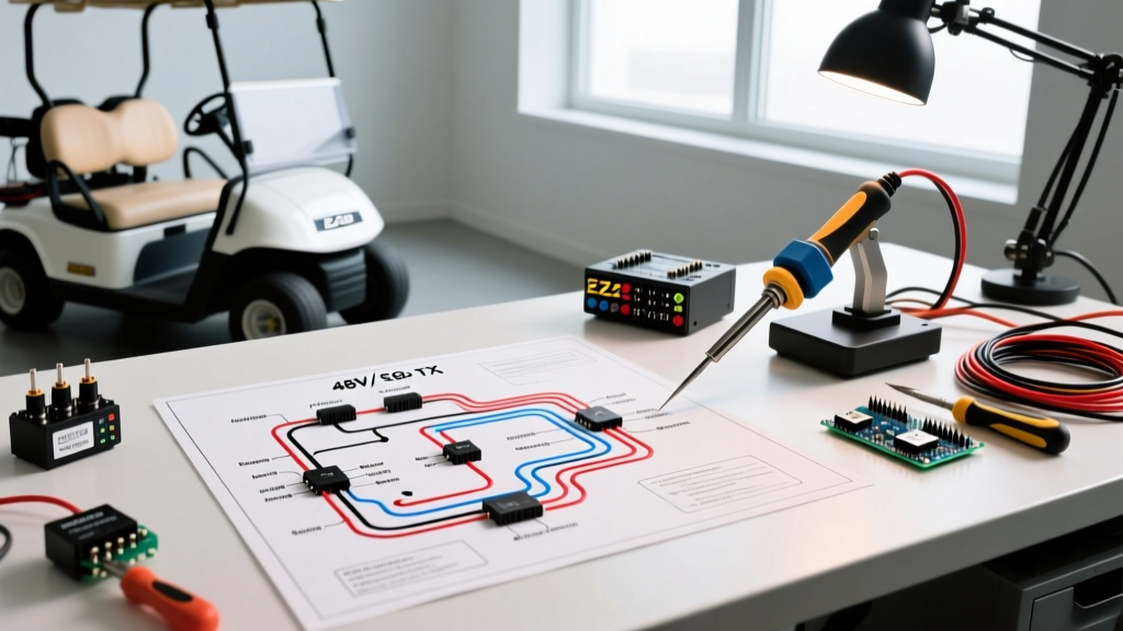
Navigating an EZ-GO electric golf cart wiring schematic can feel like deciphering a foreign language, especially when transitioning from basic 12V automotive systems to high-current 48V DC traction networks. Whether you are maintaining a classic 36V TXT, troubleshooting a 48V Precision Drive System (PDS), or upgrading an RXV, the schematic is your ultimate diagnostic map. In 2026, with the surge in aftermarket lithium conversions and high-torque motor swaps, understanding the exact logic and power flow of your cart's electrical architecture is no longer optional—it is a critical safety and operational requirement.
This comprehensive reference guide breaks down the core circuits of the ubiquitous EZ-GO TXT 48V PDS platform, detailing high-current traction loops, low-voltage logic pathways, and specific component pinouts. We will also cover advanced edge cases, such as precharge resistor failures and lithium BMS integration.
⚠️ HIGH-CURRENT DC WARNING: A fully charged 48V EZ-GO battery bank can deliver over 400 amps of short-circuit current. Unlike AC, DC arcs do not self-extinguish at zero-crossing. Always disconnect the main negative battery cable and use insulated tools when probing high-current nodes. Reference the NFPA 70 National Electrical Code for proper DC wire gauge and overcurrent protection standards.Core Architecture: Series vs. PDS vs. RXV
Before tracing wires, you must identify your cart's control architecture. EZ-GO primarily utilized three distinct electrical topologies for their electric fleet:
- Series System (Pre-2000s 36V): The field and armature of the motor are wired in series. Speed is controlled by varying the voltage via a resistor-based V-Glide or early PWM controller. These lack regenerative braking and rely on a separate mechanical brake.
- PDS (Precision Drive System) (2000-2014 48V): Uses a Separately Excited (SepEx) motor. The controller independently manages the armature and field windings, allowing for regenerative braking, multiple speed profiles via a plug-and-play map switch, and electronic roll-away protection.
- RXV (2008-Present 48V/72V): Features an AC induction motor driven by a Danaher or Curtis AC controller. The wiring schematic here is vastly different, utilizing a 3-phase power output and an encoder feedback loop rather than traditional DC brushes and commutators.
This guide focuses heavily on the 48V PDS TXT, as it remains the most common platform for DIY wiring repairs and aftermarket modifications today.
Tracing the High-Current Traction Loop
The high-current loop is responsible for delivering raw power from the battery bank to the motor. In a 48V PDS system, this circuit utilizes heavy 2 AWG or 4 AWG welding cable to minimize voltage drop and resistive heating.
Step-by-Step Power Flow Trace
- Battery Pack (+): Power leaves the positive terminal of the battery bank (typically 4x 12V AGM/Lithium or 6x 8V Flooded Lead-Acid) via a 2 AWG red cable.
- Main Solenoid (Line Side): The cable terminates on the large left terminal of the main contactor (usually an Albright SW200 or equivalent 48V heavy-duty solenoid).
- Main Solenoid (Load Side): When the coil is energized, the internal copper disc bridges the gap, sending 48V+ out of the large right terminal.
- Controller B+ (Pin 1): The power enters the Curtis 1206MX controller at the main positive stud.
- Controller M- (Pin 2): The controller modulates this DC voltage via internal MOSFETs and outputs a pulsed DC wave to the motor's A2 terminal.
- Motor A1 to F&R Switch: The current exits the motor at A1, travels to the Forward and Reverse (F&R) mechanical switch, which dictates polarity, and finally returns to the Battery Pack (-).
The Low-Current Logic & Control Circuit
While the high-current loop moves the cart, the low-current circuit (using 14 to 16 AWG wire) tells the controller when and how to move. The logic circuit operates on the same 48V potential but draws minimal amperage.
Key Switch and Safety Interlocks
When you turn the key, 48V is routed to the F&R switch microswitches. The cart will only engage if the F&R lever is fully seated in Forward or Reverse, closing the internal microswitch. From there, power flows through the seat safety switch (if equipped) and into the Motor Controller Output Regulator (MCOR).
The MCOR (Throttle) Mechanism
Older EZ-GO carts used a V-Glide assembly with physical microswitches and a potentiometer. Modern PDS carts use the MCOR (Motor Controller Output Regulator), specifically the MCOR4 in later models. The MCOR uses a Hall-effect sensor or a sealed potentiometer to send a 0-5V analog signal to the controller's throttle input pin. If the MCOR spring fatigues or the internal wiper track wears out, the controller will register a 'High Pedal Disable' (HPD) fault and refuse to close the main solenoid.
Curtis 1206MX Controller Pinout Reference
The Curtis 1206MX is the brain of the PDS system. Understanding its pinout is essential for reading any EZ-GO electric golf cart wiring schematic. Below is the standard mapping for the main logic harness.
| Pin / Stud | Wire Color | Function | Voltage / Signal |
|---|---|---|---|
| B+ (Stud) | Red (2 AWG) | Main Battery Positive Input | 48V - 58V DC |
| B- (Stud) | Black (2 AWG) | Controller Logic Ground | 0V Reference |
| M- (Stud) | Yellow (2 AWG) | Motor Armature Output | Pulsed DC (0-48V) |
| J1 Pin 1 | Black/White | Throttle Low (Return) | 0V |
| J1 Pin 2 | Green/White | Throttle High (Input) | 0.8V - 3.4V DC |
| J1 Pin 5 | Red/White | 5V Sensor Supply | 5V DC Output |
| J2 Pin 1 | Blue | Solenoid Coil Driver (+) | 48V Output (When active) |
| J2 Pin 3 | Yellow | Forward Input | 48V Input (From F&R) |
| J2 Pin 4 | Green | Reverse Input | 48V Input (From F&R) |
Troubleshooting: The 'No Solenoid Click' Diagnostic
The most common issue referenced in EZ-GO service manuals is the 'dead pedal'—you press the throttle, but the main solenoid fails to click, and the cart does not move. Using the schematic, we can isolate this in three steps:
- Verify Solenoid Coil Power: Set your multimeter to DC Volts. Probe the two small terminals on the solenoid. Have a helper press the pedal with the key ON and F&R in Forward. You should read full pack voltage (approx. 50V). If you read 0V, the issue is upstream (Key switch, F&R microswitch, or Tow/Run switch).
- Check the Controller Logic Ground: If the solenoid has 48V on both small terminals but won't click, the controller is not completing the ground path. The Curtis controller internally switches the ground side of the solenoid coil. Check the 16-pin harness for broken ground wires.
- Test the MCOR Throttle Sweep: If the solenoid clicks but the motor doesn't spin, backprobe J1 Pin 2 (Throttle Input). With the key ON, slowly press the pedal. The voltage should smoothly sweep from roughly 0.8V up to 3.4V. If it jumps erratically or stays at 0V, the MCOR is defective.
Critical Edge Case: The Precharge Resistor
One of the most vital, yet frequently omitted, components in the EZ-GO wiring schematic is the precharge resistor. This is typically a 250-ohm, 2-watt ceramic resistor wired in parallel across the two large terminals of the main solenoid.
Why is it necessary? Inside the Curtis controller are large electrolytic capacitors. When the solenoid closes, these capacitors act as a dead short until they charge. Without the precharge resistor to slowly trickle-charge the capacitors a millisecond before the main solenoid contacts close, the massive inrush current will cause a severe DC arc. Over time, this arc will pit and eventually weld the solenoid contacts together, causing the cart to run away uncontrollably.
2026 Pricing Note: A replacement 250-ohm precharge resistor costs less than $5, whereas replacing a welded Albright SW200 solenoid and a damaged controller MOSFET bank can exceed $650.
Schematic Adjustments for Lithium (LiFePO4) Upgrades
As of 2026, over 60% of aging EZ-GO TXT carts are being retrofitted with 48V LiFePO4 battery kits (typically ranging from $1,200 to $1,800 installed). This requires specific deviations from the OEM lead-acid wiring schematic:
1. Bypassing the OEM Charger Interlock
The OEM Delta-Q or Lester charger communicates with the PDS controller via a specific pin on the charge receptacle to prevent the cart from being driven while plugged in. Many aftermarket lithium chargers do not support this proprietary handshake. You must wire a standard 48V SPST relay into the charge receptacle circuit to manually break the solenoid coil ground when the charger is connected.
2. Integrating the BMS Low-Voltage Cutoff (LVC)
Lithium batteries will be permanently destroyed if discharged below their safe threshold (usually 2.5V per cell). The Battery Management System (BMS) includes an LVC relay trigger. You must wire the BMS discharge cutoff relay in series with the solenoid coil ground. If the BMS detects a low-voltage event, it opens the relay, instantly dropping out the main solenoid and cutting power to the controller, protecting the cells.
Authoritative Resources & Further Reading
For deeper technical specifications, always consult the manufacturer data sheets and recognized electrical standards:
- Curtis Instruments Motor Speed Controllers - Official documentation for the 1206MX and 1236E controller pinouts, fault codes, and programming parameters.
- Flight Systems Inc. Golf Cart Motors - Industry-leading diagnostic data on SepEx and Series DC motor testing, field winding resistance values, and brush replacement intervals.
Frequently Asked Questions (FAQ)
Can I use a 12V automotive solenoid on my 48V EZ-GO?
No. A standard 12V continuous-duty solenoid will overheat and fail rapidly on a 48V system. Furthermore, automotive solenoids are not rated for the 300+ amp inrush currents required by golf cart traction motors. You must use a heavy-duty golf cart contactor rated for at least 400A peak and 48V DC coil voltage.
Why does my cart jerk forward when I release the brake?
This is usually caused by a failing MCOR throttle assembly or a worn throttle return spring. If the controller reads a throttle voltage above the HPD (High Pedal Disable) threshold of roughly 0.8V upon startup, it will lock out. However, if the voltage flutters just below the threshold due to a weak spring, the controller may intermittently engage the motor. Inspect the MCOR mechanical linkage immediately.
What wire gauge should I use for the battery interconnects?
According to standard DC electrical practices, 2 AWG pure copper welding cable is the minimum requirement for 48V golf cart battery interconnects and main power runs up to 4 feet. For runs exceeding 4 feet, or if you have upgraded to a high-torque motor drawing over 400A, step up to 1/0 AWG to prevent voltage sag and cable overheating.