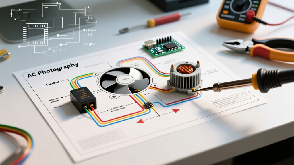

Understanding PIR Technology and the BISS0001 Chip
Passive Infrared (PIR) sensors are the backbone of modern automated lighting and security systems. Whether you are building a custom microcontroller-based security node or retrofitting a 120V commercial lighting circuit, understanding the exact wiring diagram for a PIR sensor is critical for reliable operation. At the core of most low-voltage DIY PIR modules is the BISS0001 signal processing IC, which translates analog pyroelectric sensor data into clean digital logic pulses. For high-voltage applications, the sensor is integrated into a wall switch housing with built-in triacs or relays to handle mains AC loads.
In this comprehensive reference guide, we break down the wiring schematics for both the ubiquitous HC-SR501 low-voltage module and standard 120V/240V mains PIR wall switches (such as the Lutron Maestro MS-VPS5). We will cover logic-level shifting, potentiometer calibration, and 2026 NEC code requirements for neutral wires.
Low-Voltage Wiring Diagram for a PIR Sensor (HC-SR501)
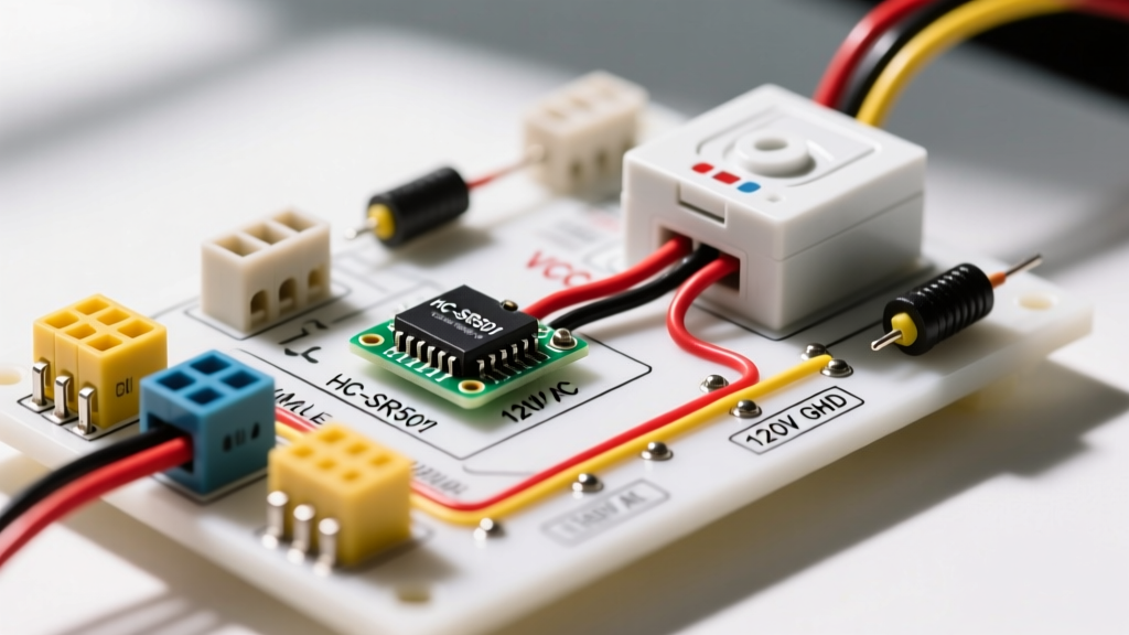
The HC-SR501 is the most widely used PIR module in the DIY electronics space, typically costing between $1.50 and $3.00 per unit. It operates on a DC input of 4.5V to 20V and outputs a digital HIGH signal when motion is detected. However, wiring it to modern 3.3V microcontrollers like the ESP32 or Raspberry Pi Pico requires careful attention to voltage levels.
HC-SR501 Pinout and Specifications
| Pin | Label | Function | Electrical Specs |
|---|---|---|---|
| 1 | GND | Ground Reference | 0V (Common ground with MCU) |
| 2 | OUT | Digital Output Signal | Outputs VCC level (e.g., 5V or 3.3V) |
| 3 | VCC | Power Input | 4.5V to 20V DC (5V recommended) |
The 3.3V Logic Level Shifting Requirement
A common failure mode in DIY projects is frying the GPIO pin of a 3.3V microcontroller. The HC-SR501's OUT pin outputs the same voltage as its VCC input. Because the BISS0001 chip operates most reliably at 5V, you should power the VCC pin with 5V. However, sending a 5V HIGH signal directly into an ESP32 GPIO pin will destroy the silicon.
Expert Wiring Fix: You must implement a simple voltage divider on the OUT pin before it reaches your 3.3V microcontroller. Use a 1.8kΩ resistor (R1) in series with the OUT pin, and a 3.3kΩ resistor (R2) connected from the GPIO junction to GND. This drops the 5V signal down to a safe ~3.23V logic HIGH.
Calibration: Time Delay and Sensitivity Potentiometers
The HC-SR501 features two onboard trimmer potentiometers and a jumper block that dictate its behavior:
- Time Delay Potentiometer: Adjusts how long the OUT pin stays HIGH after motion ceases. Fully counter-clockwise yields approximately 0.3 seconds. Fully clockwise extends the delay to roughly 200 seconds. The timing curve is non-linear; the first 25% of the rotation covers the 0.3s to 5s range.
- Sensitivity Potentiometer: Adjusts the detection range. Fully counter-clockwise limits detection to ~3 meters. Fully clockwise extends the Fresnel lens focal range to ~7 meters.
- Trigger Jumper (H vs L): The 'H' position enables retriggerable mode (the timer resets with every new motion detection). The 'L' position enables non-retriggerable mode (the timer runs out regardless of continuous motion, followed by a ~2.5 second lockout period where the sensor is blind).
For a deeper dive into the pyroelectric effect and raw sensor integration, refer to the Adafruit PIR Sensor Learning Guide.
High-Voltage Mains Wiring Diagram for a PIR Sensor (120V/240V)
When moving from microcontrollers to architectural lighting, the wiring diagram for a PIR sensor changes drastically. Modern commercial and residential PIR wall switches (like the Lutron Maestro MS-VPS5, retailing around $32.00) handle 120V-277V AC loads. In 2026, the electrical landscape has shifted heavily toward low-wattage LED fixtures, which fundamentally changes how PIR switches must be wired.
The Neutral Wire Dilemma and 2026 NEC Updates
Historically, many PIR switches were '2-wire' devices that leaked a small amount of current through the lighting load to power their internal microcontrollers. With incandescent bulbs, this was invisible. With modern LED drivers, this leakage causes 'ghosting' (LEDs flickering or glowing when the PIR switch is OFF).
To solve this, modern PIR switches require a dedicated Neutral (White) wire. Under the 2026 National Electrical Code (NEC) Article 404.2(C), a neutral conductor is now strictly mandated at nearly all switch locations to support advanced sensors and smart home controls. Always verify the presence of a neutral bundle in the back of your switch box before purchasing a 3-wire PIR switch.
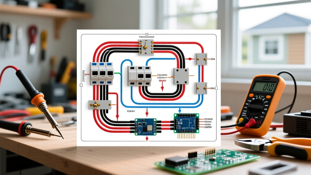
Step-by-Step 120V PIR Wall Switch Wiring
- Kill the Power: Turn off the 15A or 20A breaker at the main panel and verify zero voltage using a non-contact voltage tester (NCVT) and a multimeter.
- Identify the Wires: Locate the Line (Hot/Black from breaker), Load (Switched Leg/Black or Red to fixture), Neutral (White bundle), and Ground (Bare/Green).
- Connect Ground: Attach the PIR switch's Green ground wire to the bare copper ground bundle using a wire nut.
- Connect Neutral: Connect the PIR switch's White (or Blue, depending on manufacturer) neutral wire to the bundle of white neutral wires in the box. Do not connect this to the ground.
- Connect Line (Hot): Attach the PIR switch's Black (Line) wire to the incoming hot wire from the breaker.
- Connect Load: Attach the PIR switch's remaining wire (often Red or Blue, labeled Load) to the wire leading up to the light fixture.
- Box Fill Check: PIR switches have deep housings. Ensure your electrical box meets NEC Article 314.16 volume requirements. A standard single-gang box (18 cubic inches) is usually sufficient, but a deep 22.5 cubic inch box is highly recommended to prevent crushing the 14 AWG wires.
Advanced Troubleshooting and Edge Cases
Even with a perfect wiring diagram for a PIR sensor, environmental and electrical edge cases can cause erratic behavior. Here is how to diagnose the most common professional-level failures:
1. False Triggers from Thermal and RF Interference
PIR sensors do not 'see' motion; they detect rapid changes in infrared heat signatures. If your HC-SR501 or mains switch is triggering with no one in the room, check for:
- HVAC Vents: A sudden blast of warm air from a register crossing the sensor's field of view will mimic a human body. Reposition the sensor or use electrical tape to mask the lower facets of the Fresnel lens.
- Direct Sunlight: Afternoon sun hitting the sensor dome can saturate the pyroelectric element. Avoid west-facing window placements.
- RF Interference: The high-gain amplifier inside the BISS0001 chip is notoriously susceptible to 2.4GHz Wi-Fi and Bluetooth RF noise. If your ESP32's Wi-Fi antenna is within 2 inches of the HC-SR501 dome, the RF emissions will induce false HIGH signals on the OUT pin. Maintain at least a 4-inch physical separation or shield the sensor's PCB with grounded copper tape.
2. Mains LED Flickering and Minimum Load Requirements
When wiring a 120V PIR switch to a single 9W LED bulb, the switch's internal relay or triac may fail to latch properly due to insufficient current draw. According to the U.S. Department of Energy's guidelines on occupancy sensors, always verify the switch's 'Minimum Load' specification. If your PIR switch requires a 15W minimum load and you are switching a 9W LED, you must install a load compensation resistor (often sold as a 'bypass capacitor' or 'dummy load' by manufacturers like Lutron or Leviton) in parallel with the fixture at the ceiling canopy.
3. The 'Lockout' Period Misunderstanding
Many DIYers believe their HC-SR501 is broken because it refuses to trigger immediately after a previous event. If the jumper is set to 'L' (Non-retriggerable), the sensor enforces a mandatory 2.5 to 3-second hardware lockout after the timer expires. This allows the internal op-amps to recalibrate to the ambient room temperature. If your application requires immediate, continuous re-triggering (like an automated desk lamp), you must set the jumper to 'H' (Retriggerable).
Summary of Best Practices
Whether you are wiring a 5V DC microcontroller node or a 120V AC commercial lighting circuit, the key to a successful PIR installation lies in respecting the electrical boundaries of the hardware. Always use logic level shifters for 3.3V microcontrollers, ensure your switch boxes have dedicated neutral wires for modern LED compatibility, and physically isolate the sensor dome from HVAC drafts and RF antennas. By following these precise wiring diagrams and calibration steps, your motion-sensing infrastructure will deliver years of flawless, automated performance.