
Understanding the Standard Wiring Diagram for Thermostats
Deciphering a wiring diagram for thermostats is a foundational skill for any DIY electrician, HVAC technician, or homeowner upgrading to a modern smart climate control system. Unlike standard 120V or 240V line-voltage circuits, residential central HVAC systems rely on a 24VAC (Volts Alternating Current) low-voltage control circuit. This control circuit is stepped down from the main power supply via a transformer located in the air handler or furnace, and it uses the thermostat as a series of mechanical or solid-state relays to trigger high-voltage contactors, gas valves, and blower motors.
In 2026, the transition to high-resolution smart thermostats—such as the ecobee SmartThermostat Premium or the 4th Generation Nest Learning Thermostat—has made understanding these low-voltage diagrams more critical than ever. Modern units require continuous power for Wi-Fi radios, occupancy sensors, and vivid displays, shifting the industry away from legacy 'power-stealing' methods and making the common wire (C-wire) a strict requirement for reliable operation.
CRITICAL SAFETY WARNING: Before touching any thermostat wires, turn off the power at BOTH the main electrical panel (for the air handler/furnace) and the exterior disconnect box (for the AC condenser). While the thermostat wires carry a relatively safe 24VAC, accidentally shorting the 'R' (hot) wire to any other terminal can instantly blow the 3-amp or 5-amp automotive-style blade fuse located on your furnace's main control board (e.g., Honeywell ST9120U or White-Rodgers 50M56U), killing your entire HVAC system until the fuse is replaced.
The Universal HVAC Terminal & Color Code Matrix
While the NFPA 70 (National Electrical Code) does not strictly mandate specific colors for low-voltage thermostat wires, the HVAC industry has adopted a universal color-coding standard. Below is the definitive reference matrix for standard residential forced-air systems.
| Terminal | Standard Wire Color | Function & Destination | Electrical State (When Calling) |
|---|---|---|---|
| R / Rc / Rh | Red | 24VAC Hot (Power from Transformer) | Constant 24VAC |
| C | Blue or Black | 24VAC Common (Return Path) | Constant 0V (Reference) |
| W / W1 | White | Stage 1 Heat (Gas Valve / Electric Heat) | 24VAC sent to heating relay |
| Y / Y1 | Yellow | Stage 1 Cool (Compressor Contactor) | 24VAC sent to AC contactor |
| G | Green | Indoor Blower Fan Relay | 24VAC sent to fan relay |
| O / B | Orange | Heat Pump Reversing Valve | Energized on Cool (O) or Heat (B) |
| W2 / Aux | Black or Brown | Stage 2 / Auxiliary Electric Heat | 24VAC sent to heat strips |
2-Wire Thermostat Wiring Diagram (Heat Only)
The 2-wire configuration is the simplest diagram, typically found in older homes with gravity furnaces, basic gas valves, or millivolt gas fireplaces. It utilizes only the R and W terminals.
How the 2-Wire Circuit Operates
- Red Wire (R): Connects to the 'R' terminal on the thermostat and the 24V hot side of the furnace transformer.
- White Wire (W): Connects to the 'W' terminal and routes to the gas valve or heating relay.
When the ambient temperature drops below the setpoint, the internal bimetallic strip or solid-state relay inside the thermostat closes the circuit between R and W. This completes the 24VAC loop, energizing the gas valve solenoid and initiating the ignition sequence. Edge Case: If you are wiring a millivolt fireplace (which generates its own tiny voltage via a thermopile and does not use a 24V transformer), you must use a specialized millivolt thermostat. Standard 24V smart thermostats will not function on a millivolt circuit without an external 24V transformer isolation relay.
4-Wire Configuration: The Legacy Standard & Power Stealing
A 4-wire diagram adds cooling and fan control to the mix: R, W, Y, and G. This was the gold standard for homes built between 1980 and 2010 that did not utilize advanced programmable thermostats.
When upgrading a 4-wire system to a modern Wi-Fi thermostat, you will encounter the infamous 'power stealing' issue. Without a C-wire to complete the circuit, smart thermostats attempt to trickle-charge their internal lithium-ion batteries by allowing a tiny amount of current (usually 20-40 milliamps) to leak through the 'Y' or 'W' circuits when the system is idle. According to ENERGY STAR guidelines for smart thermostats, this parasitic draw can cause the AC contactor to chatter, the compressor to short-cycle, or the thermostat to drop Wi-Fi connectivity and reboot randomly. If you have a 4-wire setup, running a new 18/5 thermostat cable from the air handler to the wall plate is highly recommended.
5-Wire Thermostat Wiring Diagram: The 2026 Smart Home Standard
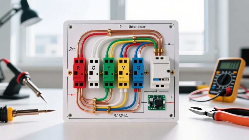
The 5-wire diagram is the modern baseline for any smart climate control installation. It includes the critical C (Common) wire. The C-wire connects directly to the 'C' terminal on the furnace control board, providing a dedicated 24VAC return path. This allows the thermostat to draw continuous power (typically 1 to 3 VA) without passing current through the HVAC relays.
Solving the Missing C-Wire Problem
If your wall cavity lacks a spare wire to use as a Common, you have two primary engineering solutions:
- Pull New Cable: Replace the old 18/4 cable with a new 18/5 or 18/8 shielded thermostat wire. This costs roughly $0.15 to $0.30 per foot for high-quality copper wire and guarantees long-term reliability.
- Use a Wire Multiplier (Adapter): Devices like the Venstar ADD-A-Wire (ACC0410) or the Fast-Stat Common Maker use high-frequency diodes and rectifiers to multiplex the R and C signals over a single existing wire. These kits cost between $15 and $25 and are installed at both the thermostat baseplate and the furnace control board. While effective, they add points of failure and are not recommended for high-draw systems with complex communicating boards.
Heat Pump Edge Cases: The O/B Terminal Logic
When reading a wiring diagram for thermostats connected to an air-source heat pump, the O/B terminal introduces a critical manufacturer-specific variable. This terminal controls the 4-way reversing valve, which dictates whether the system is in heating or cooling mode.
- Energize on Cool (O Terminal): Used by the vast majority of manufacturers, including Rheem, Ruud, Goodman, and Lennox. The 24VAC signal is sent to the reversing valve only when cooling is demanded. The default, unenergized state of the valve is 'Heat'.
- Energize on Heat (B Terminal): Used primarily by Trane, American Standard, and some older Carrier/Bryant models. The valve requires 24VAC to shift into heating mode. The default, unenergized state is 'Cool'.
Troubleshooting Tip: If your heat pump blows cold air in the winter and hot air in the summer, your O/B logic is inverted. On digital smart thermostats, this is fixed in the software installation menu (often labeled 'Heat Pump Reversing Valve: O or B'). On older mechanical thermostats, you must physically move the orange wire from the O terminal to the B terminal, or flip a micro-switch on the back of the unit.
Multimeter Diagnostics: Verifying Your Wiring
Before snapping the thermostat onto the wall plate, use a digital multimeter set to AC Voltage (VAC) to verify the transformer output and relay logic. The U.S. Department of Energy emphasizes that proper commissioning of HVAC controls prevents premature compressor failure and energy waste.
Step-by-Step Voltage Testing
- Transformer Health Check: Place your red probe on the R wire and your black probe on the C wire. You should read between 24.0 VAC and 28.0 VAC. If you read 0V, check the 3A/5A fuse on the control board. If you read 12V or 14V, your transformer is failing or shorted, and must be replaced (typically a 40VA transformer, costing around $15-$25).
- Relay Open State: Place the red probe on R and the black probe on W. With the thermostat NOT calling for heat, you should read 24 VAC. This is because the multimeter is completing the circuit through the high-impedance gas valve coil.
- Relay Closed State: Force the thermostat to call for heat. The internal relay closes. The voltage across R and W should now drop to near 0 VAC (usually 0.2V to 0.5V), as the voltage is now being dropped across the gas valve solenoid itself, not the thermostat.
Summary of Best Practices
Successfully interpreting and executing a wiring diagram for thermostats requires more than just matching colors to letters. It requires an understanding of the underlying 24VAC control logic, the specific mechanical requirements of your outdoor unit (especially for heat pumps), and the continuous power demands of modern smart home ecosystems. Always label your wires with painter's tape before removing the old unit, verify your control board fuse rating, and never guess the O/B orientation without consulting the outdoor unit's manufacturer data plate.