
The Fundamentals of Three Phase Electric Motor Wiring
Wiring a three phase induction motor correctly is the difference between decades of reliable industrial operation and a catastrophic, smoke-filled failure within seconds of startup. Whether you are integrating a new 10 HP compressor or retrofitting a legacy conveyor system, understanding three phase electric motor wiring is non-negotiable for electrical professionals and advanced DIYers.
In 2026, the shift toward high-efficiency IE4 and IE5 motors and advanced Variable Frequency Drives (VFDs) has made proper termination, phasing, and cable selection more critical than ever. This tutorial breaks down the exact configurations, National Electrical Code (NEC) requirements, and real-world troubleshooting techniques for standard dual-voltage motors.
Decoding Motor Leads: 9-Lead vs. 12-Lead Configurations
The most common point of confusion in motor wiring is opening the peckerhead (conduit box) and finding a tangled nest of unmarked wires. In North America, the NEMA MG-1 standard dictates lead markings. You will typically encounter two types of dual-voltage motors:
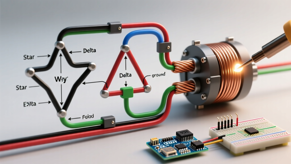
- 9-Lead Motors: Dual voltage (usually 230V/460V). These are internally connected in either Wye (Star) or Delta at the factory. You cannot change the internal topology; you can only change the external voltage configuration.
- 12-Lead Motors: Dual voltage, but capable of being wired in either Wye or Delta externally. Often used for reduced-voltage starting (Wye-Delta starting) or dual-voltage applications (230V/460V or 380V/415V).
Identification Tip
Always use a digital multimeter (like the Fluke 87V) to verify lead continuity before applying power. If the factory tags are missing, you must map the coils. A 9-lead motor will show continuity in specific groups of three, whereas a 12-lead motor will show continuity in pairs.
Configuration Matrix: Star (Wye) vs. Delta
Understanding the electrical differences between Star and Delta configurations is vital for matching the motor to your facility's power supply and starting requirements.
| Characteristic | Star (Wye) Configuration | Delta Configuration |
|---|---|---|
| Line Voltage vs. Phase Voltage | Line = √3 × Phase | Line = Phase |
| Starting Current | Lower (approx. 33% of Delta) | Higher (Full across-the-line) |
| Starting Torque | Lower (approx. 33% of Delta) | High (100% rated torque) |
| Primary Application | High-voltage runs, soft-start needs | Low-voltage runs, high-torque loads |
| Neutral Point | Yes (can be grounded/monitored) | No neutral point available |
Step-by-Step: Wiring a 9-Lead Dual Voltage Motor
Let's look at the most common scenario: wiring a 9-lead, 230/460V motor. Always verify the internal connection type on the nameplate.
Scenario A: 9-Lead Wye (Star) Motor
For High Voltage (460V):
- Tie leads T4 and T7 together and insulate with a wire nut and heat shrink.
- Tie leads T5 and T8 together and insulate.
- Tie leads T6 and T9 together and insulate.
- Connect L1 to T1, L2 to T2, and L3 to T3.
For Low Voltage (230V):
- Group and tie T1, T4, and T7 together. Connect L1 to this group.
- Group and tie T2, T5, and T8 together. Connect L2 to this group.
- Group and tie T3, T6, and T9 together. Connect L3 to this group.
Scenario B: 9-Lead Delta Motor
For High Voltage (460V):
- Tie T1 and T6 together (L1 connects here).
- Tie T2 and T4 together (L2 connects here).
- Tie T3 and T5 together (L3 connects here).
- Insulate T7, T8, and T9 individually (they are not used in high-voltage Delta).
For Low Voltage (230V):
- Tie T1, T6, and T7 together. Connect L1.
- Tie T2, T4, and T8 together. Connect L2.
- Tie T3, T5, and T9 together. Connect L3.
Expert Warning: Never assume a motor is Wye or Delta based on its physical size or brand. A 5HP Baldor-Reliance motor might be Wye, while a 5HP WEG motor of the same era might be Delta. The nameplate diagram is the absolute source of truth.
NEC Compliance and Wire Sizing for 2026
Sizing conductors for three phase electric motor wiring is strictly governed by NEC Article 430. The most common mistake DIYers and junior electricians make is sizing the wire based on the nameplate current. This is a code violation.
Per NEC 430.22, conductors must be sized at 125% of the motor's Full Load Amps (FLA) as listed in NEC Tables 430.247 through 430.250, not the nameplate.
Real-World Sizing Example
Assume you are wiring a 15 HP, 460V, 3-phase motor.
- Nameplate current: 19.5A
- NEC Table 430.250 FLA: 21A
- Calculation: 21A × 1.25 = 26.25A
According to the 75°C column of NEC Table 310.16, you must use 10 AWG THHN/THWN-2 copper wire (rated for 35A). Using 12 AWG (rated 25A) based on the nameplate current would result in an undersized, non-compliant, and potentially dangerous installation.
2026 Material Cost Note: As of early 2026, the price of copper THHN wire remains elevated. Expect to pay approximately $1.15 to $1.35 per foot for 10 AWG copper, and roughly $0.75 per foot for 12 AWG. Always factor in current market pricing when estimating industrial retrofit jobs.
Modern VFD Integration and Inverter-Duty Wiring
In modern industrial setups, across-the-line starting is being rapidly replaced by Variable Frequency Drives (VFDs) like the Yaskawa GA800 or Allen-Bradley PowerFlex 525. When wiring a motor to a VFD, standard practices change:
- Voltage Matching: If your VFD is a 230V output model, the motor must be wired in the low-voltage configuration, regardless of the incoming line voltage to the drive.
- Cable Selection: Standard THHN wire is susceptible to corona discharge and insulation breakdown due to the high-frequency PWM (Pulse Width Modulation) switching of modern VFDs. You must use specialized Inverter-Duty cable (e.g., Belden VFD2XL) which features an overall shield and robust XLPE insulation to handle dV/dt voltage spikes.
- Grounding: VFD cables utilize a symmetrical ground design (typically 3 ground wires) to prevent bearing fluting caused by common-mode shaft currents. Ensure the motor's shaft grounding ring is intact.
Troubleshooting and Failure Modes
Even with perfect wiring, environmental factors and grid anomalies can cause failures. Here is how to diagnose the most common three phase motor issues using professional diagnostic tools.
1. Single-Phasing
If one phase is lost while the motor is running, it will continue to spin but will draw massive current on the remaining two phases, leading to rapid thermal destruction of the windings.
- Diagnosis: Use a Fluke 435 Power Quality Analyzer to check for current imbalance. A variance of more than 5% between phases indicates a problem (loose contactor, blown fuse, or utility issue).
- Prevention: Install a phase-monitoring relay (like the Macromatic MP800 series) in the control circuit to drop out the contactor if phase loss or severe imbalance occurs.
2. Phase Reversal
Swapping any two of the three power leads will reverse the motor's direction. While harmless to the motor electrically, it can destroy mechanical equipment like screw compressors or scroll pumps.
- Fix: Simply swap L1 and L2 at the motor terminal block or the VFD output terminals (never swap inputs to a VFD to reverse direction; use the VFD's digital input programming instead).
3. Insulation Breakdown
Moisture, heat, and VFD voltage spikes degrade winding insulation over time.
- Testing: Use a Megohmmeter (Megger). For a 460V motor, apply 1000V DC for one minute. According to the Fluke motor troubleshooting guidelines, a reading below 1 Megohm indicates compromised insulation that requires rewinding or replacement. A healthy motor should read well over 100 Megohms.
Final Thoughts on Safe Motor Termination
Mastering three phase electric motor wiring requires a meticulous approach to lead identification, NEC compliance, and modern VFD compatibility. Always refer to the Department of Energy's Premium Efficiency Motor Selection and Sizing Guide for deeper insights into system efficiency and proper matching. By utilizing the correct wire sizing, terminating leads with the proper torque (typically 35-40 in-lbs for standard 10-14 AWG terminal screws), and verifying phasing before startup, you ensure the longevity and safety of your electromechanical systems.