
The Complexity of the Ford Super Duty Electrical System
When you are upfitting a heavy-duty truck for commercial work, towing a 5th-wheel RV, or installing auxiliary lighting, understanding the wiring diagram for Ford F250 models is non-negotiable. The 2017 through 2026 Super Duty generations feature highly integrated CAN-bus networks, Pulse Width Modulated (PWM) trailer brake controllers, and high-amperage upfitter circuits. A generic automotive wiring approach will lead to blown fuses, voltage drop, or worse, a chassis fire.
This comprehensive reference guide bypasses the fluff and dives straight into the exact wire gauges, factory color codes, and troubleshooting matrices required to safely modify or repair your F250’s electrical harness. Whether you are wiring a snowplow, a winch, or a heavy-duty trailer, these specifications reflect the current OEM standards and best practices for high-draw DC environments.
Core Wire Gauge Standards for the F250 Chassis
Automotive wire is typically sized according to SAE J1128 standards, which dictate different ampacity thresholds compared to standard AC household wiring. Because truck harnesses are exposed to high under-hood temperatures and long routing distances (especially on 8-foot beds and crew cabs), you must oversize your wire gauge to compensate for voltage drop.
| Wire Gauge (AWG) | Max Amperage (SAE) | Common F250 Application | Recommended Fuse/Breaker |
|---|---|---|---|
| 14 AWG | 15A | Tail lights, clearance markers, upfitter trigger pigtails | 10A - 15A |
| 12 AWG | 20A | Turn signals, reverse lights, short-run electric brake power | 15A - 20A |
| 10 AWG | 30A | Factory 7-way trailer brake output, 12V auxiliary feed | 30A |
| 8 AWG | 40A - 50A | Upfitter switch high-load relays, battery charge lines | 40A - 50A |
| 4 AWG | 100A+ | Main alternator to battery, heavy winch power feeds | 120A+ Mega Fuse |
| 1/0 AWG | 150A+ | Secondary battery grounding, high-output alternator upgrades | ANL Fuses |
Expert Insight: According to Marine Electrical Ampacity References, DC voltage drop becomes critical beyond 10 feet of total wire length (positive and negative combined). If you are running a 12V feed to a camper shell on a long-bed F250, upgrade from the factory 10 AWG to 8 AWG to maintain a minimum of 12.2V at the load.
Decoding the 7-Way Trailer Wiring Diagram for Ford F250
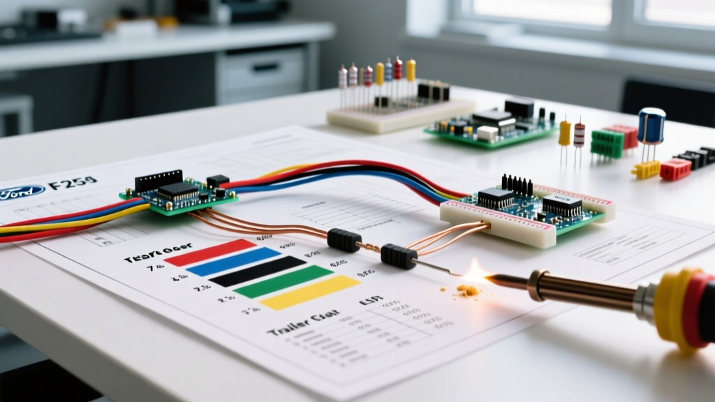
The factory 7-pin RV blade connector at the rear bumper is the most frequently modified and troubleshooted component on the truck. While the physical pinout follows the SAE J2862 / RVIA standard, the factory wire colors under the chassis sometimes differ from standard aftermarket trailer wiring. Below is the definitive color code and gauge matrix for the F250 7-way plug.
- Pin 1 (Ground): White wire, 10-8 AWG. Note: Must be grounded to a bare metal frame point, not the powder-coated bed.
- Pin 2 (Electric Brakes): Blue wire, 10 AWG. Carries the PWM signal from the Integrated Trailer Brake Controller (ITBC).
- Pin 3 (Tail/Running Lights): Brown wire, 14-12 AWG. Protected by a 30A fuse in the under-hood BJB (Battery Junction Box).
- Pin 4 (12V Battery Feed): Black wire, 10-8 AWG. Often gated by a relay that only energizes when the ignition is in the 'Run' position.
- Pin 5 (Right Turn/Stop): Green wire, 12 AWG.
- Pin 6 (Left Turn/Stop): Yellow wire, 12 AWG.
- Pin 7 (Reverse/AUX): Purple wire, 12 AWG. Commonly used for reverse lockout solenoids on surge brake trailers.
The ITBC PWM Signal Warning: The factory Ford ITBC module does not send a simple 12V analog signal to the trailer brakes; it sends a high-frequency PWM signal. If you are installing an aftermarket controller (like a Tekonsha Prodigy P3), you cannot simply splice into the blue brake wire. You must use a Ford-specific plug-and-play adapter (e.g., Tekonsha 22292) that interfaces with the OBD-II CAN-bus or properly intercepts the factory module wiring behind the driver's kick panel to avoid triggering a U0424 dash fault code.
Upfitter Switch Wire Colors and Gauge Reference (2017-2026)
Modern F250 trucks feature up to six auxiliary (AUX) upfitter switches located on the overhead console or dash. These switches do not carry the full load of your accessories; instead, they provide a low-amp 12V trigger signal to high-amperage relays located in the under-hood power distribution box.
Trigger Wire Color Codes (Under-Hood Pigtails)
To connect your relays, locate the blunt-cut wire pigtails taped to the main harness near the driver-side fender. The standard color codes for the 2017-2026 generation are:
- AUX 1 (30A Relay): Yellow with Light Green tracer
- AUX 2 (30A Relay): Light Green with White tracer
- AUX 3 (30A Relay): Grey with Black tracer
- AUX 4 (30A Relay): Grey with Orange tracer
- AUX 5 (40A Relay): Purple with White tracer
- AUX 6 (40A Relay): Purple with Black tracer
These trigger wires are typically 14 AWG. The actual high-current power for these circuits is drawn directly from the B+ battery stud via heavier gauge wires (usually 10 AWG for the 30A circuits and 8 AWG for the 40A circuits) routed through the factory relays.
Common Wiring Failure Modes and Troubleshooting
Even with a perfect understanding of the wiring diagram for Ford F250 models, environmental factors and factory design bottlenecks cause recurring electrical issues. Here are the most common failure modes and their engineered solutions.
1. Trailer Battery Not Charging (Voltage Drop on Pin 4)
The Problem: Many owners report that their trailer’s breakaway battery or house batteries fail to charge while driving. The factory 10 AWG black wire running from the under-hood relay to the rear 7-way plug spans over 25 feet. Under a 15A draw, this results in a voltage drop of nearly 1.5V, leaving only 12.5V at the trailer plug—insufficient to charge a 12.8V lithium or AGM battery bank.
The Fix: Bypass the factory charge line. Run a dedicated 6 AWG marine-grade tinned copper wire from the under-hood B+ stud (protected by a 50A inline circuit breaker) directly to the 12V feed pin on the 7-way plug. As noted by etrailer's Comprehensive Wiring FAQ, upgrading the charge wire gauge is the single most effective modification for heavy RV towers.
2. Chafing Near the Spare Tire Carrier
The Problem: The main harness routing to the rear bumper and 7-way plug passes directly over the spare tire crossmember. Over years of vibration and road debris impact, the factory loom rubs through, causing short circuits that blow the 30A trailer lighting fuses.
The Fix: Inspect the harness wrap above the spare tire. If the corrugated loom is compromised, strip it back, inspect the 12 AWG and 14 AWG wires for copper exposure, and repair using adhesive-lined IP67 heat shrink. Reroute the harness slightly and secure it with UV-resistant P-clamps and rubber edging trim.
3. Grounding to Powder-Coated Frames
The Problem: The F250 frame is heavily powder-coated from the factory. Accessories grounded directly to the frame via standard ring terminals will experience high resistance, leading to flickering lights and erratic sensor readings.
The Fix: Always use a wire brush or sanding flap to remove the powder coat down to bare steel before attaching a ground ring terminal. Immediately coat the terminal and bare metal with dielectric grease or a dedicated zinc-rich cold galvanizing compound to prevent flash rust. Alternatively, utilize the factory-provided ground studs located near the spare tire winch and the rear bumper brackets.
Expert Splicing and Extension Protocols
When extending the F250 chassis harness for custom truck beds, crane mounts, or extended wheelbase modifications, twist-connectors and electrical tape are strictly prohibited. The undercarriage environment demands waterproof, vibration-proof terminations.
- Adhesive-Lined Heat Shrink: Use 3M or Ancor marine-grade dual-wall heat shrink. The inner adhesive melts and seals the splice against moisture and road salt.
- Deutsch Connectors: For modular accessories (like removable snowplows or winch controllers), use Deutsch DT or DTM series connectors with silicone wedge locks. These provide an IP68 seal and handle high vibration.
- Soldering vs. Crimping: While soldering provides excellent conductivity, it can make the wire brittle under constant chassis vibration. For high-vibration zones (suspension components, steering columns), use high-quality ratchet crimpers with open-barrel terminals. For static harness extensions, a solder seal splice is preferred.
By strictly adhering to these wire gauge specifications, color codes, and routing protocols, you ensure that your F250's electrical system remains reliable, safe, and capable of handling the extreme demands of modern heavy-duty towing and upfitting. Always consult the official Ford Super Duty Specifications and your specific year's Body Builder Layout Book before tapping into primary CAN-bus or SRS (airbag) circuits.