
Understanding the 24VAC Control Circuit
Every residential split-system air conditioner relies on a low-voltage control circuit to communicate between the wall-mounted thermostat, the indoor air handler (or furnace), and the outdoor condenser unit. Unlike the 120V or 240V line voltage that powers the compressor and blower motors, the control circuit operates on 24 volts alternating current (24VAC) stepped down via a control transformer. Understanding the standard thermostat wiring diagram for AC is critical for both installing basic programmable units and upgrading to modern Wi-Fi-enabled smart thermostats.
CRITICAL SAFETY WARNING: Always shut off the 120V/240V main disconnect at the breaker panel and the outdoor condenser disconnect before handling thermostat wires. Accidentally shorting the 24VAC 'R' (Hot) wire to the 'C' (Common) wire or any grounded metal surface will instantly blow the 3-amp ATC automotive fuse located on your indoor HVAC control board, requiring a board-level repair.
Standard 5-Wire AC Thermostat Diagram Reference
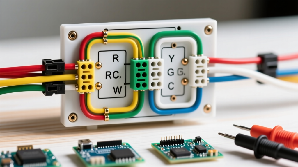
The most common configuration for a standard central air conditioning system paired with a single-stage gas furnace is the 5-wire setup. Below is the definitive reference matrix for terminal designations, standard color codes, and circuit functions.
| Terminal | Standard Wire Color | Circuit Function | Destination / Component |
|---|---|---|---|
| R (or Rh/Rc) | Red | 24VAC Power (Hot) | Control Transformer (Indoor) |
| Y (or Y1) | Yellow | First Stage Cooling Call | Outdoor Contactor Coil & Indoor Board |
| G | Green | Indoor Blower Fan Relay | Indoor Air Handler Fan Relay |
| W (or W1) | White | First Stage Heating Call | Gas Valve / Furnace Ignition Control |
| C | Blue or Black | 24VAC Common (Return) | Control Transformer (Completes Circuit) |
Deep Dive: Terminal Logic and Operations
- R (Power): This is the 24VAC 'hot' leg. In older systems, you might see a jumper wire between Rh (Heating power) and Rc (Cooling power). Modern digital thermostats handle this internally, but if your system uses separate transformers for heat and cool (rare in modern residential builds), the jumper must be removed.
- Y (Cooling): When the ambient temperature rises above the setpoint, the thermostat closes the internal relay between R and Y. This sends 24VAC down the yellow wire to the outdoor condenser's contactor coil, pulling the high-voltage contacts closed to start the compressor and condenser fan.
- G (Fan): Closing the R-G circuit energizes the indoor blower relay. In cooling mode, the thermostat automatically closes G alongside Y. However, G can be triggered independently for continuous air circulation without engaging the outdoor compressor.
- W (Heating): Sends 24VAC to the furnace control board to initiate the ignition sequence. This terminal is bypassed during pure AC cooling operations.
The C-Wire Dilemma in 2026 Smart Thermostats
If you are upgrading to a modern smart thermostat in 2026—such as the Ecobee Smart Thermostat Premium (retailing around $249) or the Google Nest Learning Thermostat 4th Gen (retailing around $279)—the C (Common) wire transitions from optional to strictly mandatory.
Older mechanical thermostats were 'dumb' switches requiring no continuous power. Smart thermostats contain Wi-Fi radios, high-resolution touchscreens, and occupancy sensors that draw between 1.5 to 3 watts of continuous power. Without a dedicated C-wire to complete the 24VAC circuit, these devices attempt 'power stealing.' They trickle a small current through the Y or W circuits while the HVAC is off to charge their internal lithium-ion batteries.
Failure Modes of Power Stealing
- Contactor Chatter: The trickle voltage can partially energize the outdoor AC contactor coil, causing it to rapidly click on and off (chatter). This will pit and destroy the high-voltage contacts, leading to a $150-$250 contactor replacement.
- Micro-Shorts on Control Boards: Modern high-efficiency furnaces (like the Carrier Infinity series) feature sensitive logic boards. Power stealing can induce voltage sags that corrupt the board's EEPROM or trigger phantom error codes.
- Thermostat Reboot Loops: During extreme summer heat, the AC runs continuously. If the thermostat is stealing power via the Y wire, but the Y wire is actively energized by the HVAC call, the thermostat loses its charging path, dies, and reboots, dropping your home's cooling.
For comprehensive guidelines on smart HVAC controls and energy efficiency, refer to the U.S. Department of Energy's thermostat guide and the EPA ENERGY STAR certified smart thermostat criteria.
Advanced Configurations: Heat Pumps and 2-Stage AC
While the 5-wire diagram covers basic setups, many modern homes utilize heat pumps or 2-stage compressors. According to data from the Air-Conditioning, Heating, and Refrigeration Institute (AHRI), variable-speed and multi-stage systems now account for over 40% of new residential installations.
| Terminal | Color | Application |
|---|---|---|
| Y2 | Light Blue | Second-stage cooling (2-stage compressors) |
| O/B | Orange | Reversing valve for Heat Pumps (O for Rheem/Ruud, B for most others) |
| Aux / E | Brown | Emergency electric heat strips (bypasses heat pump) |
| S1 / S2 | Shielded | Outdoor temperature sensor (prevents heat strips from running in mild weather) |
Wire Gauge Selection and Physical Routing
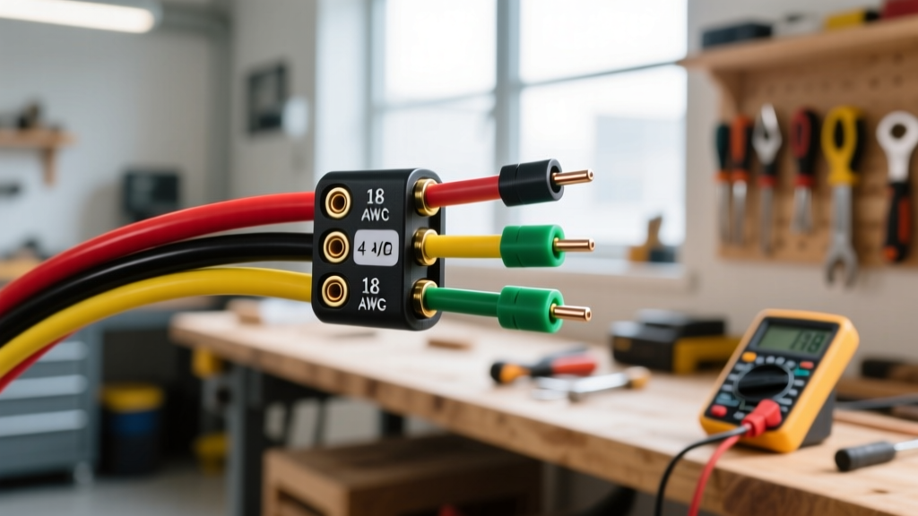
Do not use standard 14 AWG or 12 AWG Romex (NM-B) cable for thermostat runs. The industry standard is 18 AWG solid copper thermostat wire, typically sold in 5-conductor (18/5) or 8-conductor (18/8) bundles.
- Why Solid Core? HVAC control boards and thermostat backplates use screw-terminal blocks designed to clamp down on solid wire. Stranded wire (like speaker wire) will fray, loosen over time due to thermal expansion/contraction, and cause intermittent 'No Power' or 'AC Not Blowing Cold' faults.
- Why 18 AWG? The 24VAC control circuit draws less than 1 amp of current. 18 AWG wire is rated for up to 14 amps in chassis wiring and easily handles the 50-foot to 100-foot runs typical in residential construction without experiencing voltage drop that would prevent the outdoor contactor from pulling in.
Step-by-Step Wiring and Verification Procedure
Follow this exact sequence to ensure a safe and functional installation:
- Kill the Power: Turn off the breaker for the indoor air handler/furnace and pull the outdoor disconnect block.
- Label and Photograph: Before removing the old thermostat, take a high-resolution photo of the existing wiring. Wrap painter's tape around each wire and label it with the terminal letter (not the old wire color, as previous installers often ignored color codes).
- Strip and Seat: Use a precision wire stripper to remove exactly 1/4 inch of insulation. Insert the wire into the terminal block and tighten the set screw until snug. Give the wire a gentle tug to verify the mechanical grip.
- Multimeter Verification: Before mounting the new thermostat, turn the indoor breaker back on. Set a digital multimeter (such as the Fluke 117) to AC Volts. Place the red probe on the R wire and the black probe on the C wire. You should read between 24.0V and 28.0V AC. If you read 0V, the 3A fuse on the control board is blown or the transformer is dead.
- System Test: Mount the thermostat, restore all power, and enter the installer setup menu to configure the equipment type (e.g., 1-stage cool, 1-stage heat, gas furnace). Trigger a cooling call and verify the outdoor fan and compressor engage within 3 to 5 minutes (accounting for the built-in compressor short-cycle delay).
Troubleshooting Matrix: Common AC Wiring Faults
| Symptom | Probable Wiring Fault | Diagnostic Action |
|---|---|---|
| Thermostat screen is completely blank | Missing C-wire, blown 3A board fuse, or tripped float switch breaking the R or C circuit. | Check R to C voltage at the board. If 0V, inspect the condensate overflow switch and the 3A automotive fuse. |
| Indoor blower runs, but outdoor AC unit does not turn on | Broken Y wire, loose Y terminal connection, or failed outdoor contactor coil. | Measure 24VAC between Y and C at the outdoor contactor. If voltage is present but contactor doesn't pull in, replace the coil. |
| AC blows warm air, but outdoor unit runs | Thermostat is incorrectly wired to O/B instead of Y, or reversing valve is stuck (Heat Pump specific). | Verify Y terminal has 24VAC during a cool call. Check if O/B terminal is erroneously energized. |
| Thermostat clicks rapidly, AC turns on and off every few seconds | Power stealing on a Y-wire without a C-wire, causing voltage drop at the contactor. | Install a dedicated C-wire or a 24VAC C-wire adapter kit at the air handler. |
By strictly adhering to the standard thermostat wiring diagram for AC and verifying your 24VAC control voltages with a multimeter, you eliminate 95% of common HVAC installation errors. Always prioritize the physical integrity of your 18 AWG solid copper connections and ensure your smart thermostat has a dedicated common wire to protect your expensive outdoor compressor components.