
Mastering Single Wide Mobile Home Electrical Wiring Diagrams for Installation Planning
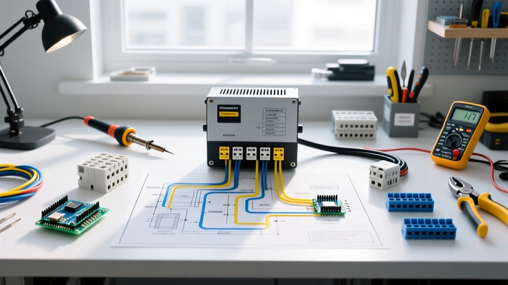
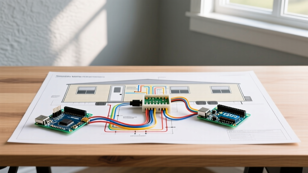
When planning an electrical overhaul or new installation for a manufactured housing unit, relying on standard site-built home schematics is a critical error. Single wide mobile home electrical wiring diagrams operate under a distinct set of federal regulations, spatial constraints, and structural realities. Unlike traditional stick-built homes governed entirely by the National Electrical Code (NEC), manufactured homes must comply with the HUD Code (24 CFR Part 3280, Subpart I). Understanding how to read and interpret these specialized diagrams is the foundation of a safe, code-compliant, and functional electrical system.
This installation planning guide breaks down the anatomy of single wide mobile home electrical wiring diagrams, detailing feeder connections, branch circuit routing, and the specific failure modes that plague older units. Whether you are upgrading a 1980s 60-amp panel to a modern 200-amp service or troubleshooting a persistent ground fault, precise planning is non-negotiable.
The Regulatory Divide: HUD Code vs. NEC Standards
The most crucial concept to grasp before interpreting any single wide mobile home electrical wiring diagram is the jurisdictional boundary. The U.S. Department of Housing and Urban Development (HUD) enforces the Manufactured Home Construction and Safety Standards for the home's internal wiring up to the point of installation. Once the home is sited, the external feeder, disconnect, and grounding electrode system fall under the local authority having jurisdiction (AHJ) and the NFPA 70 National Electrical Code (NEC).
Expert Insight: A common planning mistake is treating the main panelboard inside the single-wide as a standard service panel. In most single-wide diagrams, the interior panel is actually a subpanel fed from an exterior disconnect. The neutral and ground buses MUST remain isolated inside the home, a detail frequently botched by DIYers who treat it as a primary service entrance.
Core Components in Single Wide Wiring Schematics
When you unroll a factory schematic or draft a retrofit plan, you will identify three primary zones. Properly sizing and mapping these zones ensures your load calculations align with 2026 energy demands.
1. The Exterior Disconnect and Feeder Junction
Single wide diagrams typically begin at the weatherhead or underground pedestal. The feeder cable (often 4/4/2/6 Aluminum USE-2 for a 200A service) routes to an exterior NEMA 3R disconnect box. From there, it passes through the steel I-beam chassis floor joists to a crossover junction box. This junction box is where the external feeder transitions to the internal NM-B (Romex) or THHN-in-conduit wiring that feeds the interior panelboard.
2. The Interior Panelboard
HUD code strictly prohibits placing the main panelboard in bathrooms, closets, or over stairs. In a standard 14x70 single-wide, the panel is usually located in the utility closet near the water heater or HVAC air handler. When planning your diagram, ensure the panel you select (such as the Square D HOM2040M200C) has adequate physical clearance: 30 inches wide and 36 inches of deep working space, which can be challenging in narrow single-wide hallways.
3. Branch Circuit Routing Constraints
Single wide homes lack traditional attics or basements. Wiring is routed through the floor cavity (the 'belly board') or dropped down from the ceiling via interior partition walls. Your diagram must account for the fact that NM-B cable run under the chassis is exposed to moisture and physical damage. Therefore, any wiring routed below the floor joists must be upgraded to UF-B (Underground Feeder) cable or run through rigid metal conduit, a critical deviation from standard indoor wiring diagrams.
Standard Branch Circuit Requirements (2026 HUD/NEC Matrix)
Modern single wide mobile home electrical wiring diagrams must incorporate combo-type AFCI (Arc-Fault Circuit Interrupter) protection for nearly all 120V, 15A and 20A branch circuits. Below is the standard circuit matrix required for a typical 1,200 sq. ft. single-wide layout.
| Circuit Type | Amperage | Wire Gauge (Cu) | Breaker Type | HUD/NEC Reference |
|---|---|---|---|---|
| Kitchen Small Appliance (Min. 2) | 20A | 12 AWG NM-B | GFCI / Combo AFCI | 24 CFR 3280.807(d) |
| Laundry Receptacle | 20A | 12 AWG NM-B | GFCI / Combo AFCI | 24 CFR 3280.807(d) |
| Bathroom Receptacles | 20A | 12 AWG NM-B | GFCI | 24 CFR 3280.807(d) |
| General Lighting & Receptacles | 15A or 20A | 14 AWG or 12 AWG | Combo AFCI | 24 CFR 3280.807(e) |
| Electric Range | 40A - 50A | 6 AWG or 8 AWG | Standard 2-Pole | 24 CFR 3280.807(f) |
| Central HVAC / Heat Pump | 30A - 40A | 10 AWG or 8 AWG | Standard 2-Pole | NEC Article 440 |
Step-by-Step Installation Planning Workflow
To translate a single wide mobile home electrical wiring diagram into a physical installation, follow this sequential workflow.
- Perform the Article 220 Load Calculation: Do not guess the service size. Calculate the general lighting load at 3 VA per square foot. Add 1,500 VA for each of the two required kitchen small appliance circuits and 1,500 VA for the laundry circuit. Apply the NEC demand factors to determine if a 100A or 200A feeder is required. In 2026, with the prevalence of electric heat pumps and EV charging, a 200A service is the minimum recommended standard.
- Map the Belly Board Routing: Identify where circuits will drop down into the floor cavity. Mark the steel I-beams on your diagram. You cannot drill through the structural steel chassis I-beams to route wire. Your diagram must show wires routing through pre-punched factory holes or dropping down through the floor decking into the insulated belly cavity.
- Specify the Grounding Electrode System (GES): The diagram must detail two 8-foot copper ground rods driven 6 feet apart, connected to the exterior disconnect via a continuous 4 AWG bare copper conductor. The interior panel's ground bus must be bonded to the home's steel chassis frame using a minimum 8 AWG copper bonding jumper.
- Plan for Aluminum-to-Copper Transitions: If you are using aluminum feeder cable (standard for cost savings on 200A runs) but your interior panel and branch circuits are copper, your diagram must specify a NEMA 3R junction box under the home utilizing Polaris insulated tap connectors or MAC (Mechanical Aluminum Connector) blocks with antioxidant paste to prevent galvanic corrosion.
Common Wiring Diagram Failure Modes & Edge Cases
When auditing existing single wide mobile home electrical wiring diagrams or inspecting older homes, watch for these catastrophic failure modes:
- The 'Floating Neutral' Subpanel Error: Older diagrams often show the neutral and ground bonded inside the interior panel. If the home is fed from an exterior disconnect, this creates a parallel neutral path on the grounding wires, electrifying the home's steel chassis and plumbing. The bonding screw or strap must be removed from the interior panel.
- Pre-1970s Aluminum Branch Wiring: Homes built in the 1960s and 70s often used 12 AWG solid aluminum branch wiring. This metal expands and contracts at a different rate than brass or copper terminals, leading to arcing and fires. If your diagram reflects this, plan for a complete re-wire with copper NM-B, or use only CO/ALR rated receptacles and Alumiconn pigtails.
- Undersized Feeder Cables: A frequent edge case is a 200A interior panel fed by 2/4/4 aluminum mobile home feeder (USE-2), which is only rated for 150A. Always verify the feeder cable jacket printing against the main breaker size.
- Improper Belly Board Protection: Standard NM-B cable resting on the dirt or hanging loosely in the damp belly cavity will wick moisture into the walls. Diagrams must specify UF-B cable or flexible metallic tubing (FMT) for any run below the floor joists.
2026 Material Cost Estimates for a 1,200 Sq Ft Single-Wide Retrofit
Accurate budgeting requires current market data. Below is a baseline material cost estimate for completely replacing the interior wiring and panel of a 1,200 sq. ft. single-wide home, excluding the exterior feeder and disconnect.
| Material Category | Specific Product / Spec | Estimated 2026 Cost |
|---|---|---|
| Main Interior Panelboard | Square D HOM2040M200C (200A, 40-Space) | $195.00 |
| Branch Wiring (12 AWG) | Southwire 250-ft coil 12/2 NM-B (3 coils) | $420.00 |
| Branch Wiring (14 AWG) | Southwire 250-ft coil 14/2 NM-B (2 coils) | $230.00 |
| Circuit Breakers | Mix of 15A/20A AFCI, GFCI, and standard QO/HOM | $650.00 |
| Receptacles & Switches | Leviton Decora 20A TR/GFCI (Qty 35) | $280.00 |
| Junction & Splicing | Polaris Tap Connectors, Wire Nuts, Metal Boxes | $145.00 |
| Total Interior Materials | Excluding exterior feeder, conduit, and labor | ~$1,920.00 |
Final Planning Directives
Reading and executing single wide mobile home electrical wiring diagrams requires a hybrid mindset: part NEC electrician, part manufactured housing specialist. Always consult the Department of Energy's guidelines on manufactured home efficiency when integrating modern smart thermostats and heat pump loads into older chassis frameworks. Never compromise on the isolation of the neutral bus in the interior subpanel, and always verify the structural integrity of the belly board before routing new UF-B cables. Proper planning on paper prevents hazardous conditions under the floorboards.