
Electromechanical Fundamentals: Approaching Audio Switching
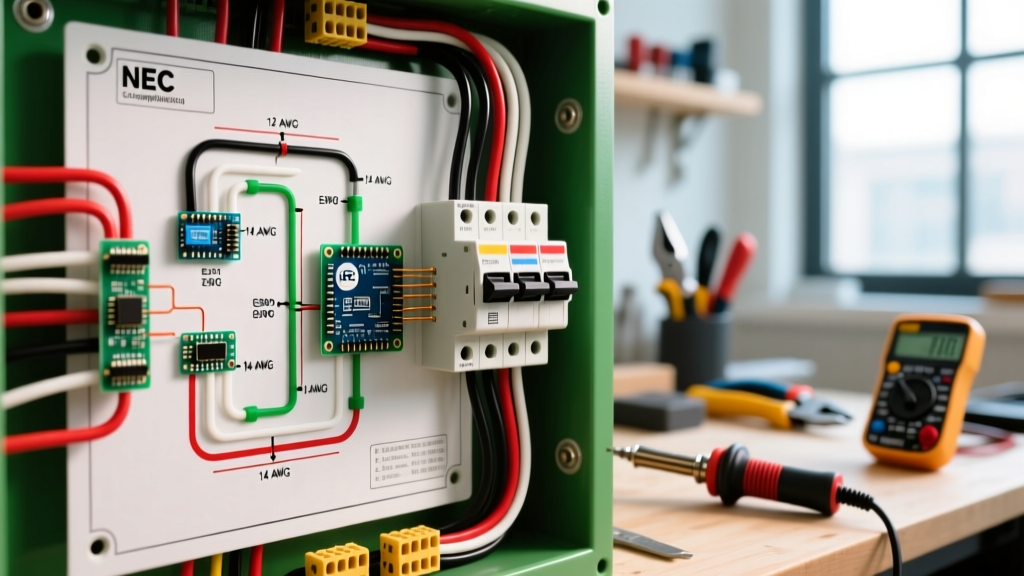
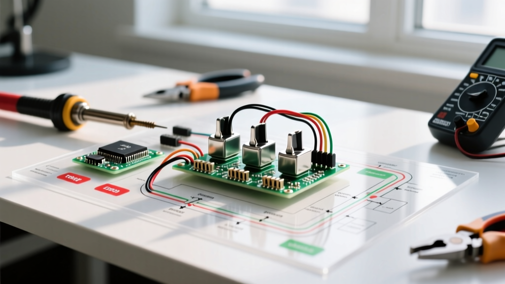
As electrical technicians who typically design motor control circuits, VFD routing, and DPDT reversing contactors, approaching audio electronics requires a shift in scale but not in fundamental electrical theory. A guitar pickup is essentially a high-impedance inductor—much like a small stepper motor coil—and the 3-way switch is a low-current electromechanical router. When analyzing the wiring diagram for telecaster 3 way switch configurations, we apply rigorous industrial wiring standards to ensure signal integrity, mechanical longevity, and thermal precision during assembly.
Unlike motor contactors that must handle high inductive kickback and back-EMF, a passive Telecaster circuit deals with millivolt AC signals and micro-ampere currents. However, the principles of contact resistance, lug thermal mass, and dielectric isolation remain identical. In this 2026 guide, we will decode the lug mapping, continuity matrices, and soldering protocols for the two industry-standard switches: the vintage-spec CRL 4-lug and the modern Oak Grigsby 4-pole 8-lug.
Switch Architecture: CRL vs. Oak Grigsby
Before grabbing your soldering iron, you must identify the physical architecture of your switch. Fender has transitioned between these two primary models over the decades, and their internal wafer mechanics dictate your wiring strategy.
| Feature | CRL 3-Way (Vintage Spec) | Oak Grigsby 4-Pole (Modern Spec) |
|---|---|---|
| Pole/Throw Config | 2-Pole, 3-Position (DP3T) | 4-Pole, 3-Position (Ganged) |
| Total Lugs | 4 Input/Output + 1 Ground | 8 Input/Output + Ground Shell |
| Contact Material | Brass / Copper Alloy | Silver-Plated Copper |
| 2026 Avg. Retail Price | $14.00 - $16.00 | $16.50 - $19.00 |
| Primary Use Case | Vintage '50s/'60s Restorations | Modern American Pro / Standard Models |
For authoritative reference on vintage and modern routing topologies, StewMac's Telecaster wiring resources provide excellent visual baselines, though we will focus here on the strict electromechanical lug mapping.
Continuity Matrices & Lug Mapping
In motor wiring, we map contactor states (Normally Open / Normally Closed) to ensure safe interlocking. For the Telecaster, we map switch positions to ensure proper pickup selection and tone circuit engagement. Below are the continuity matrices for both switch types.
Matrix A: Vintage CRL 4-Lug Switch
The CRL switch features four main lugs (numbered 1 through 4 from top to bottom when the switch is oriented with the lugs facing you and the lever pointing up/neck position).
- Position 1 (Neck): Lug 1 connects to Lug 2 (Common Output).
- Position 2 (Middle): Lug 1 and Lug 3 both connect to Lug 2 (Both Pickups Active).
- Position 3 (Bridge): Lug 3 connects to Lug 2 (Common Output).
- Lug 4: Dedicated Tone Circuit routing (typically jumpered to the volume pot casing or tone pot input depending on the exact harness schematic).
Matrix B: Modern Oak Grigsby 4-Pole 8-Lug Switch
This switch is essentially two CRL switches ganged together on a single lever, allowing independent routing of the hot signal and the ground/tone bleed. We label the left side 'A' and the right side 'B'.
| Switch Position | Side A (Pickup Selection) | Side B (Tone/Ground Routing) |
|---|---|---|
| Position 1 (Neck) | A1 connects to A-Common | B1 connects to B-Common |
| Position 2 (Middle) | A1 & A3 connect to A-Common | B1 & B3 connect to B-Common |
| Position 3 (Bridge) | A3 connects to A-Common | B3 connects to B-Common |
Note: Lugs A2 and B2 are typically left empty or used for specific treble-bleed/modern tone modifications.
Step-by-Step Soldering Protocol (IPC J-STD-001 Standards)
Soldering to heavy brass switch lugs requires managing high thermal mass, a challenge familiar to anyone who has terminated heavy-gauge motor leads. A cold solder joint on a 42 AWG pickup wire will result in high contact resistance, acting as a low-pass filter that destroys your high-frequency response.
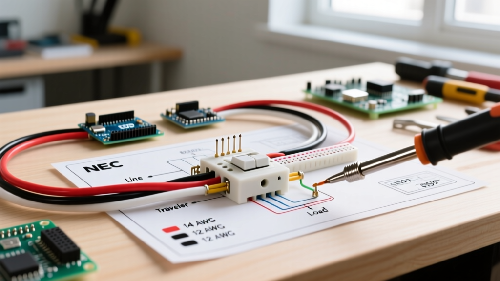
- Thermal Preparation: Set your soldering station (e.g., Hakko FX-888D or Weller WE1010) to 360°C - 380°C. Use a bevel or chisel tip (like the Hakko T18-D24) to maximize surface area contact with the lug.
- Mechanical Bonding: Unlike PCB through-hole soldering, switch lugs require a mechanical wrap. Pass the stripped AWG 22 tinned-copper ground wires and AWG 42/43 enameled pickup wires through the lug eyelets and crimp them lightly with needle-nose pliers. This prevents wire fatigue failure from lever actuation.
- Flux and Tinning: Apply a minimal amount of no-clean or rosin-core flux (Kester 245 63/37 Sn/Pb is the industry standard for its eutectic melting point of 183°C). Tin the lug first, then the wire, and finally flow them together. The joint should take no more than 2.5 seconds to prevent melting the internal nylon wafer of the Oak Grigsby switch.
- Enamel Stripping: Pickup wire is coated in polyurethane or polysol enamel. Do not scrape it with a blade, which risks nicking the copper core. Instead, use the heat of your tinned iron tip and a blob of molten solder to 'burn off' the enamel, a technique detailed in Seymour Duncan's technical wiring diagrams.
Expert Callout: Shielding and Twisted Pairs
In motor wiring, we use twisted pairs and shielded cables to reject VFD-induced common-mode noise. While a Telecaster operates at a much lower frequency, the high-impedance nature of passive pickups (often 250kΩ - 1MΩ load) makes them highly susceptible to 50/60Hz mains hum. Always route your switch-to-pot wires as tightly twisted pairs, and ensure the copper shielding tape in the control cavity is grounded to a single star-point to prevent ground loops.
Troubleshooting Common Failure Modes
Even with a perfect wiring diagram for telecaster 3 way switch layouts, physical assembly errors can cause signal degradation. Here is how to diagnose them using a digital multimeter (DMM).
1. Intermittent Signal Dropout in Position 2
The Fault: The middle position relies on the mechanical wiper bridging two adjacent lugs simultaneously. If the switch wafer is dirty or the wiper tension is weak, Position 2 will drop out.
The Fix: Do not bend the wiper tabs manually; this ruins the factory-calibrated spring tension. Instead, flush the switch internals with 99% isopropyl alcohol or a dedicated contact cleaner like DeoxIT D5. Actuate the lever 50 times to clear oxidation.
2. High-Frequency Loss (Muddy Tone)
The Fault: Stray capacitance or a cold solder joint acting as an unintended RC low-pass filter.
The Fix: Measure the DC resistance from the pickup lead at the switch lug to the output jack tip. It should read within 5% of the pickup's rated DC resistance (typically 7kΩ - 10kΩ for Telecasters). If it reads higher, reflow the solder joint at the switch lug, ensuring the rosin core has fully activated and wetted the brass.
3. Ground Loop Hum
The Fault: The switch casing (on Oak Grigsby models) is often used as a ground bus. If the casing is grounded via a lug, but the mounting nuts also ground it to a shielded pickguard, you create a loop.
The Fix: Adhere to strict IPC J-STD-001 soldering and assembly requirements regarding ground topology. Implement a star-grounding scheme where all component grounds (switch casing, bridge plate, pickup covers) return to the back of the volume potentiometer casing via dedicated wires, rather than daisy-chaining through the switch lugs.
Frequently Asked Questions
Can I use a standard 3-way light switch for a Telecaster?
No. A household 3-way light switch is an SPDT (Single Pole, Double Throw) designed for 120V/15A AC mains and lacks the multi-pole ganged architecture required to route both the audio signal and the tone circuit simultaneously. Furthermore, its mechanical throw distance and lug spacing are incompatible with guitar control plates.
Does the orientation of the switch matter?
Electrically, the switch is symmetrical. However, mechanically, Fender control plates are stamped with a specific slot orientation. If you mount an Oak Grigsby switch upside down, the lever will operate in reverse (Bridge position will physically point toward the neck). Always dry-fit the switch into the control plate before applying heat to the lugs.
What wire gauge should I use for the switch jumpers?
Use AWG 22 stranded, tinned copper wire for all ground jumpers and switch-to-pot connections. While the audio signal from the pickups arrives via ultra-fine AWG 42 magnet wire, transitioning to AWG 22 at the switch lugs provides the necessary mechanical rigidity and lowers the overall impedance of the ground return path.