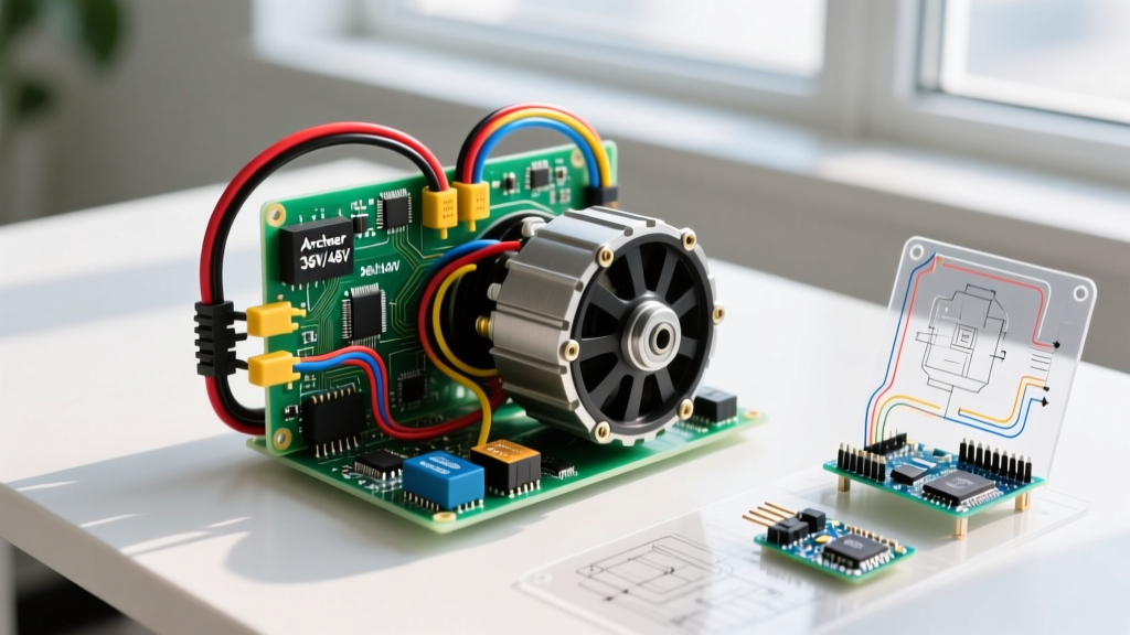

Understanding the Ancheer E-Bike Electrical Architecture
Repairing or upgrading an Ancheer electric bike requires a precise understanding of its low-voltage, high-current DC architecture. Whether you are working on a 36V 250W commuter model or a 48V 500W fat-tire variant, the fundamental wiring topology remains consistent. The system relies on a Brushless DC (BLDC) rear hub motor, a sine-wave or square-wave controller, a lithium-ion battery pack with a Battery Management System (BMS), and a suite of peripherals including the Pedal Assist Sensor (PAS), thumb throttle, and LCD display.
In this comprehensive motor wiring tutorial, we will dissect the exact ancheer electric bike wiring diagram, focusing heavily on the critical motor-to-controller connections. Incorrect wiring in a BLDC system does not merely prevent the bike from starting; it can instantly destroy the controller's MOSFETs, melt phase wires, or trigger a catastrophic battery failure.
Core Wiring Specifications and Connector Standards
Modern Ancheer models (2024 through 2026 production runs) have largely transitioned to waterproof Higo (often referred to as Julet) connectors, replacing the older, corrosion-prone screw terminals and generic SM plastic plugs. Below is the definitive reference table for wire gauges and connector types used in the Ancheer ecosystem.
| Component Circuit | Wire Gauge (AWG) | Connector Type | Max Continuous Current |
|---|---|---|---|
| Battery to Controller (Main Power) | 10 AWG or 12 AWG Silicone | XT60 / XT90 | 30A - 60A |
| Motor Phase Wires (Yellow, Green, Blue) | 12 AWG or 14 AWG Silicone | Higo L-Type (3-pin) or Bullet | 22A - 40A per phase |
| Motor Hall Sensors (5-wire bundle) | 22 AWG to 24 AWG PVC | Higo J-Type (5-pin) | < 100mA |
| Throttle / PAS / E-Brakes | 24 AWG PVC | Higo A/B-Type (3-pin/2-pin) | < 50mA |
Note: Always adhere to high-current DC safety standards. Even at 48V, a 40A draw generates significant heat. Sizing wires according to NFPA 70 (National Electrical Code) ampacity guidelines for chassis wiring is critical to prevent insulation melt-downs inside the motor axle.
The Hub Motor Wiring Diagram: Phase and Power
The BLDC hub motor used in Ancheer e-bikes operates on a 3-phase alternating current generated by the controller's internal MOSFET bridge. The motor cable exiting the left side of the rear axle contains two distinct bundles: the thick phase wires and the thin Hall sensor wires.
1. Phase Wires (The Power Trio)
The phase wires are color-coded Yellow, Green, and Blue. These carry the high-current, pulsed DC that creates the rotating magnetic field inside the stator.
- Direct Drive Hub Motors: If your Ancheer uses a direct drive hub, the phase wires connect directly from the controller to the motor stator windings.
- Geared Hub Motors: If equipped with a planetary nylon gear system, the wiring is identical, but the motor relies on an internal freewheel clutch when coasting.
CRITICAL WARNING: Never allow the exposed metal tips of the phase wires to touch each other while the battery is connected. A phase-to-phase short circuit bypasses the controller's protection, effectively shorting the battery through the motor windings. This can weld metal, vaporize copper, and cause immediate lithium battery venting. Always insulate phase wires with 3M Scotchlok or heat-shrink butt splices if extending them.
2. Hall Sensor Pinout (The 5-Wire Brain)
For the controller to know the exact rotational position of the rotor magnets, the motor uses three internal Hall effect sensors. These sensors require a 5-wire connection to the controller. According to Texas Instruments application notes on BLDC commutation, the 120-degree spatial arrangement of these sensors is vital for smooth torque delivery.
The standard Ancheer Hall sensor pinout is as follows:
- Red Wire: +5V DC (Power supply from the controller's internal voltage regulator)
- Black Wire: Ground (GND)
- Yellow Wire: Hall Signal A (Corresponds to Yellow phase wire)
- Green Wire: Hall Signal B (Corresponds to Green phase wire)
- Blue Wire: Hall Signal C (Corresponds to Blue phase wire)
Edge Case: Some older or generic replacement controllers use a 120-degree/60-degree phase angle dip switch. Ancheer motors are almost exclusively wired for a 120-degree Hall sensor configuration. If the motor stutters violently upon throttle application, the controller's phase angle setting is likely mismatched, or the Yellow and Blue signal wires are swapped.
Peripheral Wiring: PAS, Throttle, and Displays
Beyond the motor, the controller acts as a central hub for rider inputs. The wiring diagram for these peripherals relies on low-current signal wires.
Pedal Assist Sensor (PAS)
The PAS consists of a magnetic disc mounted to the crank arm and a stationary sensor zip-tied to the bottom bracket. It uses a 3-pin connector:
- Red: +5V
- Black: GND
- White/Yellow: Signal (Outputs a 0-5V square wave pulse as the magnets pass the sensor)
Pro-Tip: The air gap between the PAS magnets and the sensor must be exactly 1mm to 3mm. If the zip-tie loosens and the gap exceeds 4mm, the sensor will fail to read the magnetic field, resulting in a sudden loss of pedal assist.
Thumb Throttle and E-Brakes
The thumb throttle shares an identical 3-pin wiring scheme with the PAS (5V, GND, Signal). The motor cutoff brake levers use a simple 2-pin circuit (GND and Signal). When the brake lever is pulled, the signal pin is pulled to ground, instructing the controller to instantly cut power to the phase wires.
Real-World Troubleshooting Matrix
When an Ancheer e-bike experiences electrical failure, systematic diagnosis using a digital multimeter (DMM) is required. Do not guess; measure.
| Symptom | Probable Failure Mode | Multimeter Diagnostic Test |
|---|---|---|
| Motor stutters, makes loud grinding noise, draws massive current | Blown Hall Sensor or severed Hall wire | Set DMM to DC Volts. Backprobe the 5-pin connector while spinning the wheel by hand. Signal pins must toggle cleanly between 0V and 5V. A stuck 0V or 5V indicates a dead sensor. |
| Display turns on, but throttle and PAS do nothing | Controller 5V regulator failure or BMS lockout | Measure voltage between Red and Black wires on the throttle plug. If it reads 0V or 2.5V instead of a stable 4.9V-5.1V, the controller's internal LDO regulator is fried. |
| Motor spins backward or jerks randomly | Phase wire sequence mismatch | Verify Yellow-Yellow, Green-Green, Blue-Blue continuity from controller to motor. If using a generic replacement controller, you may need to swap the Green and Blue phase wires to match the motor's internal winding sequence. |
| Battery shuts off under heavy load (hills) | BMS over-current protection or voltage sag | Measure battery voltage at the XT60 plug while applying the throttle. If a 48V battery drops below 39V under load, the cells are degraded. Consult Battery University guidelines on series/parallel degradation for cell balancing issues. |
Soldering and Crimping Best Practices for E-Bike Repairs
Working on the Ancheer wiring diagram requires specialized physical connections. The vibration of a bicycle frame will quickly shake loose poorly executed solder joints, especially on the heavy 12 AWG phase wires.
Why You Should Avoid Soldering Phase Wires
While soldering seems like a secure connection, the high thermal mass of 12 AWG silicone wire makes it difficult to achieve a proper solder flow without overheating the copper. More importantly, solder is brittle. The constant vibration from potholes and trail riding can cause cold solder joints to fracture inside the heat shrink, leading to an intermittent phase short.
The Correct Method: Use a high-quality hex crimp tool (such as the Knipex 97 53 14 or a dedicated Higo pin crimper) paired with adhesive-lined marine-grade heat shrink. For XT60 battery connectors, soldering is acceptable and required, but you must use a minimum 60W temperature-controlled soldering station (like the Weller WE1010) set to 380°C (716°F) to ensure the joint reaches flow temperature in under three seconds, preventing heat migration into the battery cells.
Final Safety Checklist Before Powering Up
Before plugging the battery into the controller after completing your wiring repairs, execute this mandatory safety checklist:
- Visual Inspection: Ensure no bare copper is visible on any phase wire or battery terminal.
- Continuity Check: Use the DMM's continuity beep function to verify there is absolutely zero continuity between the positive and negative main power wires, and between any of the three phase wires.
- Wheel Elevation: Always place the rear wheel on a stand or flip the bike upside down before applying power. If the throttle signal is shorted or the controller is misconfigured, the bike will launch forward unexpectedly.
- Spark Pre-charge: When connecting the XT60 battery plug, touch a 100-ohm 5W resistor across the positive and negative terminals for two seconds before making the final connection. This pre-charges the controller's large electrolytic capacitors and prevents the violent spark that eventually pits and ruins the XT60 brass contacts.
By strictly following this Ancheer electric bike wiring diagram and adhering to BLDC motor theory, you can reliably diagnose, repair, and upgrade your e-bike's drivetrain, ensuring thousands of miles of safe, efficient riding.