
The Reality of Sourcing Free Car Electrical Wiring Diagrams
When a parasitic draw drains your battery or a CAN bus fault throws a U-code, guessing is not a diagnostic strategy. In 2026, dealership diagnostic fees average $185 to $225 per hour, making DIY electrical troubleshooting more financially critical than ever. However, the term "free car electrical wiring diagrams" is often a misnomer on the open web. True factory service manuals (FSM) from OEMs typically cost between $150 and $300 for a digital subscription.
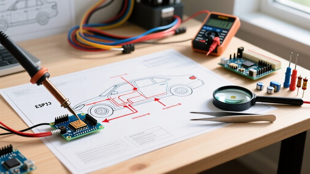
Fortunately, you can bypass these paywalls legally. Many local public libraries offer free remote access to premium databases like ChiltonLibrary or EBSCO's Auto Repair Source, which include Mitchell1 or OEM-equivalent schematics. Additionally, enthusiast forums (such as Ford-Trucks or Bimmerpost) often host archived PDF wiring manuals for specific chassis codes. Open-source initiatives like OpenGarages also provide community-driven schematic repositories for older and commercial vehicles. Before attempting any harness modification or pinout tracing, securing the correct diagram for your exact build date—not just the model year—is mandatory, as mid-year wiring revisions are common.
Decoding the Schematic: SAE vs. DIN Symbol Standards
One of the most common failure points for DIYers is misinterpreting symbols. A relay that looks like a simple switch in an American schematic might be drawn as a complex logic block in a European one. Understanding the governing standard of your vehicle's origin is crucial for accurate tracing.
| Feature | SAE Standard (US/Asian OEMs) | DIN / ISO Standard (European OEMs) |
|---|---|---|
| Wire Intersections | Dot indicates a connection; crossing lines without a dot mean no connection. | Rarely uses dots; relies on node reference numbers and alphanumeric wire labels. |
| Ground Symbols | Standard three-line descending triangle or simple chassis bolt icon. | Often uses specific numbered ground nodes (e.g., G104) linked to a physical location chart. |
| Relays & Solenoids | Drawn as physical coils and switch contacts. | Often represented by standardized DIN terminal numbers (e.g., 30, 85, 86, 87). |
| Connectors | Labeled by cavity count and letter (e.g., C205, 4-pin). | Labeled by component code and pin assignment (e.g., T10a/4). |
For a comprehensive breakdown of standardized automotive electrical symbols and testing protocols, the Society of Automotive Engineers (SAE) standards database remains the ultimate authority, defining everything from wire insulation ratings to multiplexing protocols.
Wire Color Codes, Gauge, and the Heat-Cycle Fade
Wiring diagrams rely heavily on color codes to identify circuits, but real-world conditions complicate this. A wire labeled BLK/WHT (Black with a White tracer stripe) in the diagram might look entirely dark grey under the hood of a 2018 vehicle due to years of 105°C heat cycles and oil vapor exposure. Always verify the wire gauge alongside the color to confirm you have the right circuit.
Common Automotive Wire Gauges and Applications
- 18-20 AWG: Used for 5V reference sensors, CAN bus lines, and low-current module wakes. (Typically handles under 5 amps).
- 14-16 AWG: Standard for lighting circuits, HVAC blower relays, and accessory power. (Handles 10-15 amps).
- 10-12 AWG: High-current feeds for fuel pumps, ABS modules, and main ignition feeds. (Handles 20-30 amps).
- 4-8 AWG: Starter motors, high-output alternator B+ terminals, and EV high-voltage interlock loops (HVIL).
Pro-Tip: Never pierce modern automotive wire insulation with a test light or T-pin to check for power. Piercing 18 AWG sensor wires introduces a microscopic entry point for copper oxidation, which will inevitably cause a high-resistance failure or a 5V reference drop months later. Always back-probe connectors or use insulated alligator clips.
Navigating CAN Bus Diagrams and Multiplexed Networks
Modern vehicles no longer run individual wires from every switch to the ECU. Instead, they use Controller Area Network (CAN) buses. On a wiring diagram, you will see these represented as twisted pairs labeled CAN-H and CAN-L.
When diagnosing a "Loss of Communication" code, the diagram will point you to the network topology. Most high-speed CAN networks (operating at 500 kbps) require two 120-ohm terminating resistors placed at the extreme ends of the bus. By disconnecting the battery and measuring resistance across CAN-H and CAN-L at the OBD2 port (Pins 6 and 14), your multimeter should read exactly 60 ohms (the parallel equivalent of two 120-ohm resistors). If you read 120 ohms, one resistor is missing or a module has failed open. If you read near 0 ohms, the twisted pair has shorted together, often due to harness chafing near the steering column or firewall grommet.
Step-by-Step: Voltage Drop Testing with a DMM
Reading a diagram is only half the battle; proving the circuit's integrity is the other. The most misunderstood diagnostic technique is the voltage drop test. Instead of checking for the presence of voltage, you measure the loss of voltage across a connection while the circuit is under load. According to diagnostic guidelines referenced by the National Highway Traffic Safety Administration (NHTSA) regarding electrical fire prevention, high-resistance connections are a leading cause of localized thermal events.
- Set up your Digital Multimeter (DMM): Set a high-quality meter, such as a Fluke 87V (currently retailing around $450), to DC Volts. For a deeper understanding of meter capabilities, refer to Fluke's official guide on multimeter basics.
- Activate the Circuit: The circuit MUST be flowing current. Turn on the headlights, engage the starter, or command the fuel pump via a bi-directional scan tool.
- Test the Positive Side: Place your red probe on the battery positive post and your black probe on the load's positive terminal. A healthy circuit should show a voltage drop of less than 0.2V. Anything higher indicates corrosion in the fuse box, relay contacts, or bulkhead connectors.
- Test the Negative (Ground) Side: Place your red probe on the load's ground terminal and your black probe on the battery negative post. The drop here should be less than 0.1V.
- Isolate the Fault: If you read a 0.8V drop on the positive side, move your black probe halfway back toward the battery (e.g., to the output side of the relay). When the voltage drop suddenly disappears, you have just crossed the faulty component or corroded splice.
Final Thoughts on Schematic Accuracy
Free car electrical wiring diagrams are invaluable tools, but they are only as good as your ability to interpret them. Always cross-reference the diagram's legend, verify the specific RPO (Regular Production Option) codes or build options of your exact vehicle, and rely on voltage drop testing rather than simple continuity checks. By combining accurate OEM schematics with rigorous DMM testing protocols, you can diagnose complex multiplexed faults without relying on expensive dealership diagnostics.