
Decoding the Kenmore Electric Dryer Wiring Diagram: Motor Circuit Fundamentals
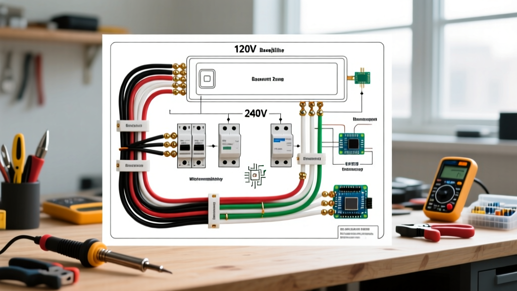
When troubleshooting a non-spinning drum or a dryer that refuses to start, understanding the Kenmore electric dryer wiring diagram is your most critical diagnostic tool. The vast majority of Sears Kenmore electric dryers (specifically the ubiquitous 110-series models like 110.60022010 and 110.82822100) were manufactured by Whirlpool. These appliances utilize a fascinating split-power architecture: while the heating element requires 240V AC, the drive motor, timer, and control circuits operate entirely on 120V AC.
This distinction is the most common stumbling block for DIYers. If you trace the 240V lines from the NEMA 14-30R terminal block expecting to find them feeding the motor, you will misdiagnose the system. The motor relies on a single 120V leg (Line 1) and a Neutral return. In this comprehensive motor wiring tutorial, we will dissect the drive motor circuit, map the 6-pin harness, and provide exact multimeter diagnostics to isolate electrical failures.
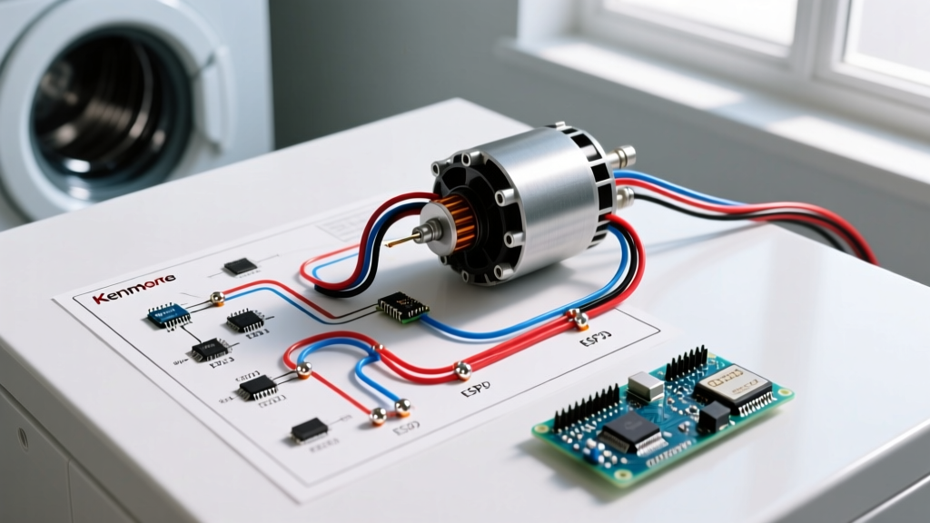
Anatomy of the Split-Phase Drive Motor
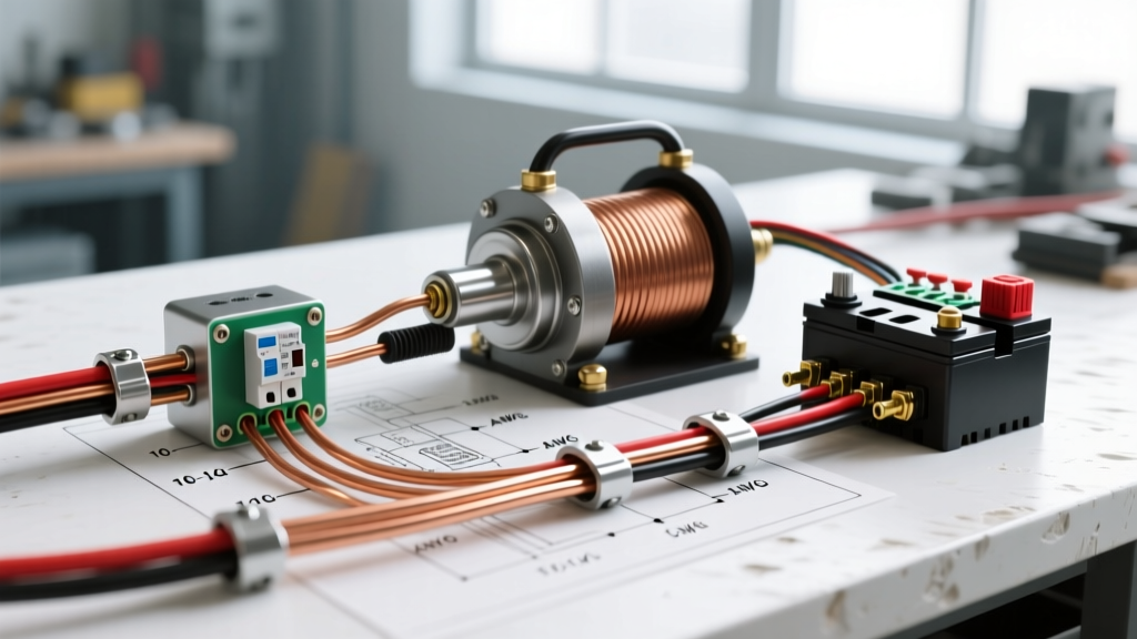
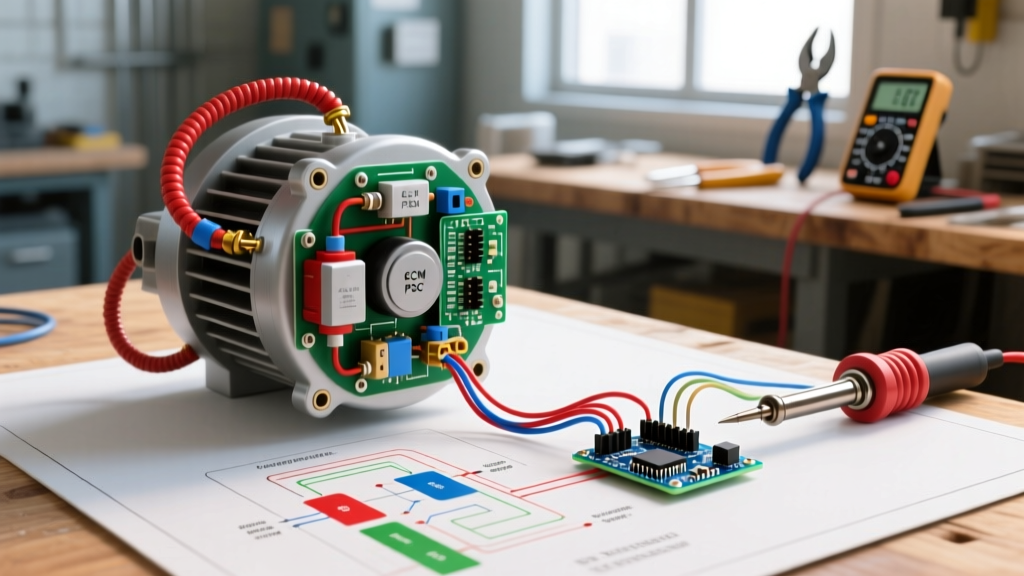
The Kenmore drive motor is a 120V, 60Hz, split-phase induction motor. Because single-phase power cannot generate a rotating magnetic field on its own, the motor utilizes two distinct windings to create the necessary phase shift for startup:
- Run Winding: Constructed with thicker gauge wire and lower resistance. It remains energized the entire time the motor is spinning, providing the continuous torque required to turn the drum and blower wheel.
- Start Winding: Constructed with thinner gauge wire and higher resistance. It provides the initial phase-shifted torque to get the rotor moving. Once the motor reaches approximately 75% of its rated RPM, a mechanical centrifugal switch physically disconnects the start winding to prevent it from overheating and melting.
Wire Color Code & Function Matrix
Before touching a multimeter, you must understand the schematic color codes. Kenmore/Whirlpool wiring diagrams adhere to a strict color standard. Refer to this matrix when tracing wires from the timer or electronic control board to the motor harness:
| Wire Color | Circuit Designation | Voltage / Function | Destination Component |
|---|---|---|---|
| Blue | L1 (Line 1) | 120V AC Hot | Timer, Motor Switch, Door Switch |
| Black | L2 (Line 2) | 120V AC Hot (240V total) | Heating Element, Motor Centrifugal Switch |
| White or White-Red | Neutral (N) | 120V Return | Motor Run Winding, Timer Motor |
| Red or White-Red | Heater Circuit | 240V Switched | Heating Element via Motor Switch |
| Tan or Yellow | Thermal Fuse / Door | 120V Control | Door Switch, Thermal Cutoff |
The Centrifugal Switch and Heater Interlock Mechanism
The most complex and misunderstood component on the Kenmore electric dryer wiring diagram is the motor's centrifugal switch. This switch performs two entirely separate, critical functions simultaneously:
- Motor Winding Management: It routes power to the start winding during the first fraction of a second of startup, then drops it out once the motor reaches operating speed.
- Heater Safety Interlock: It acts as a hardware safety gate for the 240V heating element. The L2 (Black) 120V leg destined for the heater is routed through the motor's centrifugal switch (typically terminals 3M and 4M).
Expert Insight: Why route the heater through the motor switch? If the dryer drum belt snaps, the motor will continue to spin, but the blower wheel will stop. Without airflow, the heating element would rapidly overheat and ignite the lint screen. The centrifugal switch ensures that if the motor stalls or fails to reach operating RPM, the physical contacts for the heater circuit remain open, cutting 240V power to the element. According to the National Fire Protection Association (NFPA), mechanical and electrical failures are leading contributors to dryer fires, making this interlock a vital life-safety mechanism.
Step-by-Step Motor Wiring Diagnostic Tutorial
To accurately test the motor circuit, you must isolate it from the appliance harness. Unplug the dryer from the 240V receptacle. The U.S. Consumer Product Safety Commission (CPSC) strictly advises against probing live 240V appliance terminals due to the high risk of fatal arc flash and electrocution. Always perform resistance (Ohms) testing with the power disconnected.
Step 1: Isolate the 6-Pin Motor Harness
Locate the motor and depress the locking tab on the 6-pin Molex connector. Pull the harness straight off the motor switch terminals. You are now looking directly at the motor-side pins, free from the influence of the timer, thermal fuse, or door switch.
Step 2: Test the Windings for Continuity and Resistance
Set your digital multimeter to the Ohms (Ω) setting, preferably the 200Ω range. Place your probes on the following motor-side pins:
- Run Winding Test: Measure between the Run Winding pin and the Neutral/Common pin. You should read between 10Ω and 15Ω. A reading of OL (Open Line) indicates a burnt-out run winding. A reading near 0Ω indicates a shorted winding.
- Start Winding Test: Measure between the Start Winding pin and the Neutral/Common pin. You should read between 25Ω and 30Ω. The higher resistance is normal due to the thinner gauge wire used in the start coil.
Step 3: Verify the Centrifugal Switch Operation
The centrifugal switch is mechanical and prone to lint buildup or welded contacts. With the multimeter in continuity mode (beeper on):
- Place probes on the heater interlock terminals (usually pins 3 and 4 on the motor side). With the motor at rest, the circuit should be OPEN (OL / no beep).
- Manually rotate the motor shaft or use a non-metallic tool to push the centrifugal switch actuator collar inward. The circuit should instantly close (0Ω / continuous beep).
- If the switch remains closed at rest, the contacts are welded together. This is a severe fire hazard, as the heater will receive 240V even if the motor is stalled. The entire motor assembly must be replaced.
Common Failure Modes & Edge Cases
When cross-referencing your multimeter readings with the Kenmore electric dryer wiring diagram, keep an eye out for these specific edge cases that frequently mislead technicians:
Edge Case 1: Motor Hums, Drum Won't Spin, Thermal Fuse Blows
The Symptom: You press start, the motor emits a loud 60Hz hum, the drum barely twitches, and after a few attempts, the dryer goes completely dead.
The Root Cause: The start winding is open, or the centrifugal switch is stuck in the open position. The motor is receiving 120V on the run winding but lacks the phase-shifted torque to rotate. The stalled motor rapidly draws locked-rotor amperage (LRA), overheating the housing. This heat transfers to the exhaust chute, tripping the one-time thermal fuse (usually rated for 150°C / 302°F). Fixing the thermal fuse without replacing the faulty motor switch will result in repeated failures.
Edge Case 2: Dryer Runs, But Produces Zero Heat
The Symptom: The drum spins normally, the timer advances, but the clothes remain cold and damp after 60 minutes.
The Root Cause: While many assume the heating element is burnt out, the wiring diagram reveals that the element requires L2 power routed through the motor switch. If the centrifugal switch's heater interlock contacts (3M to 4M) are pitted, oxidized, or blocked by lint, the 240V circuit remains open. Always test the motor switch interlock before ordering a new $45 heating element.
Sourcing the Exact Schematic for Your Model
Never guess wire routing based on a generic diagram. Kenmore model numbers starting with 110. indicate Whirlpool manufacturing, while 417. indicates Frigidaire/Electrolux manufacturing, which utilizes an entirely different motor architecture (often 240V motors or brushed DC motors in newer units).
To find your exact schematic, open the lower front kick-panel or the rear console panel of the dryer. Manufacturers tuck a folded, laminated tech sheet inside a plastic sleeve. This sheet contains the specific wiring diagram, diagnostic fault codes, and exact terminal block layouts for your precise serial number run. For ongoing reference regarding appliance energy efficiency and electrical standards, the U.S. Department of Energy provides excellent baseline guidelines on how modern dryer architectures manage electrical loads to minimize residential energy consumption.
Final Safety Directive
Always verify the absence of voltage with a CAT III or CAT IV rated non-contact voltage tester or multimeter before removing the terminal block cover. The neutral wire in a 240V appliance can carry lethal return current if the circuit is unbalanced or improperly wired at the breaker panel. Treat every wire as live until proven otherwise, and rely strictly on the manufacturer's wiring diagram to guide your diagnostic path.