
The Schematic Roadmap: Why Guesswork Fails Evaporative Coolers
Evaporative coolers—commonly known as swamp coolers from brands like MasterCool, Hessaire, and Portacool—operate in harsh, high-humidity, and high-heat environments. When a unit fails to blow cold air, the blower motor hums without spinning, or the water pump remains dry, amateur technicians often start swapping parts blindly. This approach inevitably leads to blown fuses, fried control boards, or severe electrical shock risks.
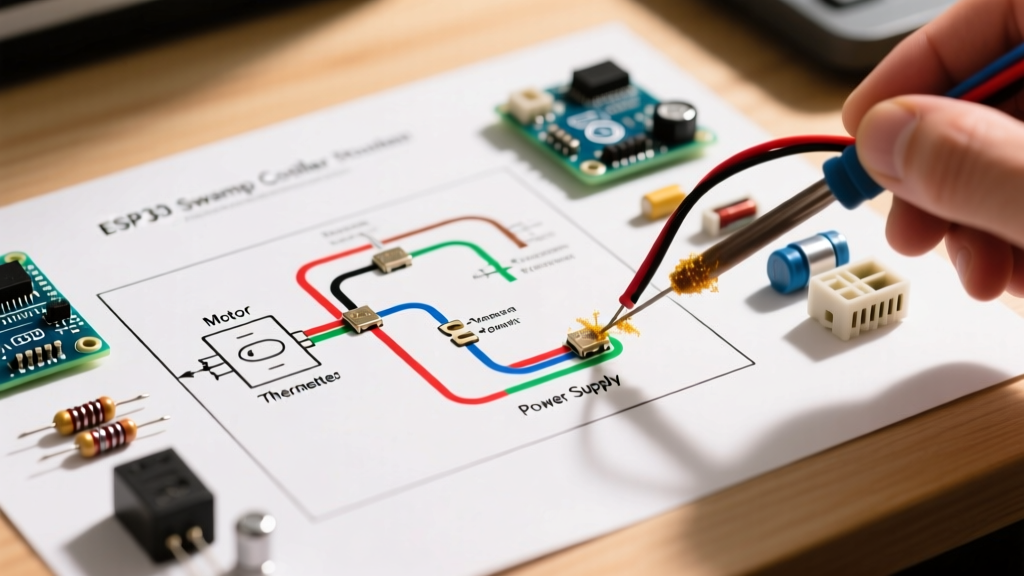
To diagnose these failures efficiently, you must treat the wiring diagram for swamp cooler systems as your primary diagnostic map. Unlike standard HVAC systems that rely on complex 24V thermostatic controls, most residential roof-mounted or portable swamp coolers operate on straightforward 120V line-voltage circuits. According to the U.S. Department of Energy, proper maintenance and electrical troubleshooting of these units can restore their efficiency to peak levels, saving homeowners hundreds of dollars in premature replacement costs.
Anatomy of a Standard 120V Swamp Cooler Schematic
Before pulling out your multimeter, you need to understand the three primary circuit branches depicted on the inside of your cooler’s electrical panel door:
- The Main Power Feed (L1 and Neutral): Typically 120V AC entering through a dedicated 15A or 20A breaker. The diagram will show the grounding path bonding to the metal chassis.
- The Blower Motor Circuit: This includes the multi-speed selector switch, the Permanent Split Capacitor (PSC) motor windings, and the run capacitor.
- The Water Pump and Control Circuit: This branch powers the submersible centrifugal pump and often integrates a pump delay relay or a digital control board (like the ASPEN series) to manage the pad-wetting cycle.
Expert Insight: Never assume the factory wiring matches the diagram perfectly. Aftermarket pump replacements or previous DIY repairs often result in swapped neutral and hot legs. Always verify the physical wiring against the schematic before applying power.
Troubleshooting Matrix: Symptoms to Schematic Nodes
Use this diagnostic matrix to map real-world symptoms directly to the nodes on your wiring diagram. Set your digital multimeter (DMM) to the appropriate AC Voltage or Ohms setting before testing.
| Observed Symptom | Schematic Node to Inspect | Multimeter Test & Expected Value | Probable Failure & Fix |
|---|---|---|---|
| Blower hums, won't spin | Run Capacitor (Brown wires) | Disconnect power, discharge cap, test capacitance (Expect 7.5 MFD ±5%) | Weak/Blown Capacitor. Replace with a 7.5 MFD 370VAC round capacitor ($14-$22). |
| Pump runs, Blower is dead | Blower Switch / Thermal Overload | Test for 120V at motor Common (White) wire while switch is ON. | Tripped internal thermal overload or burnt switch contacts. Replace 3-speed rotary switch ($18-$35). |
| Blower runs, Pump is dead | Pump Relay / Timer Board | Test for 120V at the pump receptacle spade terminals after 2-minute delay. | Failed delay relay or seized pump impeller. Replace 1/40 HP pump ($45-$85). |
| Unit trips GFCI instantly | Main Junction / Motor Windings | Megger test or Ohms test from L1 to Ground (Expect OL / Infinite). | Water intrusion in motor housing or frayed wire rubbing against chassis. |
Deep Dive: Troubleshooting the 3-Speed PSC Blower Motor
The blower motor is the most expensive component in a swamp cooler, typically costing between $110 and $180 for a 1/2 HP to 1 HP PSC (Permanent Split Capacitor) motor. The wiring diagram for swamp cooler blower circuits almost always features a 4-wire motor setup plus two brown capacitor wires.
Wire Color Decoding and Voltage Testing
When your schematic shows a 3-speed motor, the switch acts as a router for the 120V hot leg (L1). The neutral (White) is hardwired directly to the motor's common terminal.
- Black Wire (High Speed): Receives 120V when the switch is in the 'High' position. Lowest resistance winding.
- Blue Wire (Medium Speed): Receives 120V in the 'Med' position. Intermediate resistance.
- Red Wire (Low Speed): Receives 120V in the 'Low' position. Highest resistance winding.
- White Wire (Common/Neutral): Must have continuity to the neutral bus at all times.
The Diagnostic Test: If the motor does nothing on 'High' but runs on 'Low', your motor windings are likely intact, but the rotary switch contacts for the High circuit are carbon-scored and failing to pass current. Bypass the switch by temporarily jumping L1 directly to the Black motor wire. If the motor spins up to full RPM, replace the wall or panel switch.
The Run Capacitor: The Hidden Culprit
The two brown wires on your diagram lead to the run capacitor. This component provides the phase shift necessary to create a rotating magnetic field. If the capacitor degrades (common in attic or roof-mounted units where ambient temperatures exceed 130°F), the motor will draw locked-rotor amperage (LRA), overheat, and trip its internal thermal safeguard. Always test the capacitor with a dedicated capacitance meter, not just an Ohms continuity check. A reading below 7.1 MFD on a 7.5 MFD capacitor mandates immediate replacement.
Water Pump Circuit Edge Cases and Delay Relays
Modern swamp coolers utilize a pump delay feature to allow the water to saturate the aspen or rigid media pads before the blower engages. If you are troubleshooting a unit where the blower starts immediately but the pump never turns on, the wiring diagram will point you to the control module.
Testing the ASPEN Control Board
Many MasterCool and Phoenix Manufacturing units use the ASPEN digital control system. The schematic will show a 120V input to the board, and a 120V output to the pump receptacle.
- Verify Input Voltage: Probe the L1 and Neutral input terminals on the board. You must read 115V-125V AC.
- Check the Float Switch: The diagram will show the low-water cut-off float switch wired in series with the pump circuit. If the float is stuck in the 'up' (empty) position, the board will intentionally cut power to the pump to prevent dry running. Manually depress the float switch and re-test for 120V at the pump output spades.
- Inspect the Pump Receptacle: Corrosion from mineral-heavy water often destroys the female spade connectors on the pump pigtail. If voltage is present at the board but the pump is dead, strip back the wiring and install new insulated quick-disconnect terminals.
NEC Compliance and Electrical Safety Protocols
Because swamp coolers combine high-voltage electricity with continuous water flow, adherence to the National Electrical Code (NEC) is non-negotiable. NEC Article 430 governs motor circuits, dictating that the branch circuit must be rated at 125% of the motor's full-load amperage (FLA). For a standard 1/2 HP motor drawing 7.8 amps, a 15A circuit is sufficient, but a 1 HP motor drawing 14 amps requires a 20A breaker and 12 AWG copper wire.
Furthermore, because these units are often installed on roofs, in wet crawlspaces, or outdoors, NEC Article 210.8 mandates Ground Fault Circuit Interrupter (GFCI) protection. If your swamp cooler is repeatedly tripping a standard breaker, upgrading to a GFCI breaker is not just a code requirement—it is a life-saving measure against chassis energization.
Before removing any panel covers or probing any terminals, you must strictly follow OSHA Lockout/Tagout (LOTO) guidelines. Shut off the dedicated breaker at the main panel, apply a physical padlock, and verify the absence of voltage with a non-contact voltage tester (NCVT) and a live-dead-live multimeter test. Water and electricity are an unforgiving combination; let the wiring diagram guide your logic, and let safety protocols guide your hands.