
Mastering the Wiring Diagram for Bench Grinder Troubleshooting
Bench grinders are the workhorses of any metalworking or DIY shop, but when a 1/2 HP or 3/4 HP single-phase induction motor refuses to start, hums loudly, or trips your shop's 20-amp breaker, guessing the fix is a recipe for a short circuit or worse. To systematically isolate the fault, you must rely on a wiring diagram for bench grinder circuits. Whether you are working on a classic Craftsman 152.211540, a modern WEN BG4270, or an industrial Baldor 612, the underlying split-phase induction motor topology remains remarkably consistent.
In this comprehensive 2026 guide, we will decode the standard bench grinder schematic, map out the exact multimeter testing points, and provide a professional troubleshooting matrix to get your grinder spinning safely and efficiently.
Anatomy of a Standard Bench Grinder Circuit
Before probing with a multimeter, you need to understand the journey of the electrical current. A typical 120V AC bench grinder wiring diagram features five critical nodes:
- Power Entry & Grounding: The 3-prong plug delivers L1 (Hot/Black), L2 (Neutral/White), and Ground (Green/Bare). The ground must bond directly to the motor's steel stator housing.
- Toggle Switch (SPST or DPST): Usually a 15A to 20A rated switch that interrupts the L1 (Hot) leg. Some premium 2026 models use a DPST (Double Pole Single Throw) switch to isolate both Hot and Neutral for enhanced safety.
- Thermal Overload Protector: A bimetallic strip wired in series with the run winding. It opens the circuit if the motor exceeds safe operating temperatures (usually around 130°C / 266°F) and resets automatically or via a manual red button on the motor housing.
- Run Winding (Main): The heavy-gauge copper coils that sustain the motor's rotation and handle the continuous torque load.
- Start Winding & Centrifugal Switch: A lighter-gauge coil paired with a start capacitor (typically 108-130 µF). The centrifugal switch is Normally Closed (N.C.) at rest, engaging the start circuit, and opens mechanically once the rotor reaches roughly 75% of its rated 3,450 RPM.
Troubleshooting Matrix: Symptoms vs. Schematic Nodes
Use this matrix alongside your specific wiring diagram for bench grinder models to pinpoint failures. Set your digital multimeter (DMM) to the appropriate setting before testing. Always ensure the grinder is unplugged before performing continuity or resistance tests.
| Symptom | Diagram Node to Inspect | DMM Test & Expected Result | Probable Failure & Fix Cost (2026) |
|---|---|---|---|
| Completely dead; no sound | Power Cord & Toggle Switch | Continuity (Ohms) across switch terminals in 'ON' position. Expect < 1.0 Ω. | Failed toggle switch or broken L1 cord strand. ($12 - $18) |
| Motor hums loudly, won't spin | Start Capacitor & Centrifugal Switch | Capacitance (µF) across capacitor terminals. Expect 108-130 µF. If reading is 'OL' or < 80 µF, it's dead. | Blown start capacitor or stuck centrifugal switch. ($15 - $25) |
| Runs for 3 mins, then shuts off | Thermal Overload Protector | Check for physical obstruction on cooling fan. Test overload for continuity when cold (Expect 0 Ω). | Failing thermal switch or blocked ventilation. ($10 - $20) |
| Trips 20A shop breaker instantly | Run Winding & Stator Ground | Megohmmeter (Megger) or high-range Ohms between windings and motor casing. Expect 'OL' (Infinite). | Shorted stator winding to ground. (Motor replacement: $85 - $140) |
| Spins slowly, lacks torque | Run Capacitor (if equipped) | Capacitance test on run capacitor (usually 5-10 µF @ 370V). Expect exact microfarad rating ±5%. | Weak run capacitor causing phase shift loss. ($8 - $14) |
Deep Dive: Tracing the Centrifugal Switch Circuit
The most common point of failure in a bench grinder that sits unused for long periods is the centrifugal switch mechanism. On the wiring diagram, this switch is depicted in series with the start capacitor and the start winding.
How to Test the Centrifugal Switch
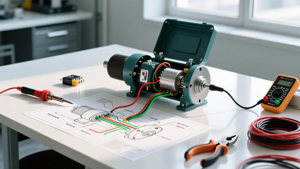
When the motor is at rest, the switch contacts must be closed. If your wiring diagram for bench grinder circuitry shows wires leading to the rear bell housing (often colored yellow and red on Baldor models), these are your switch leads.
- Step 1: Disconnect the yellow and red wires from the terminal block.
- Step 2: Place your DMM probes on the disconnected wire leads (not the motor side).
- Step 3: Insert a non-marring pry bar or thick zip-tie through the rear ventilation slots to gently push the centrifugal flyweights outward, simulating high RPM.
- Step 4: The multimeter should instantly read 'OL' (Open Line). If it remains at 0 Ω, the contacts are welded together or the spring mechanism is seized with metallic dust.
Expert Warning: If the centrifugal switch fails to open at speed, the start winding will remain energized. Because the start winding is made of thinner gauge wire not designed for continuous duty, it will overheat and melt within 10 to 15 seconds, permanently destroying the motor stator.
Safety, Grounding, and Code Compliance
When interpreting any schematic and performing repairs, adherence to electrical codes and safety standards is non-negotiable. According to the National Electrical Code (NEC), all stationary power tools with metal housings must be effectively grounded. Never use a 'cheater plug' to adapt a 3-prong grinder to a 2-prong ungrounded outlet.
Furthermore, the physical setup of the grinder is governed by strict safety regulations. As outlined by OSHA Standard 1910.215 (Abrasive Wheel Machinery), bench grinders must be equipped with properly adjusted work rests (kept within 1/8 inch of the wheel) and tongue guards (kept within 1/4 inch of the wheel) to prevent wheel fragmentation injuries. While these are mechanical requirements, a poorly wired grinder that violently shudders upon startup due to a failing start capacitor can cause the operator to lose control, making electrical troubleshooting a critical safety task.
Modern vs. Legacy Grinder Wiring Quirks
If you are restoring a vintage bench grinder (pre-2010) versus troubleshooting a 2026 model, you will notice distinct differences in the wiring diagrams:
Legacy Models (e.g., older Craftsman, Sears)
- External Start Capacitors: Often housed in a black cylindrical can mounted on the outside of the motor housing. Easy to access and test.
- Manual Reset Buttons: Thermal overloads frequently feature an external red button that physically pops out when tripped.
Modern 2026 Models (e.g., WEN, Harbor Freight Bauer)
- Internal Capacitors: To reduce manufacturing costs and footprint, modern start capacitors are often shrink-wrapped and tucked inside the rear bell housing, requiring full disassembly of the end cap to access.
- Auto-Reset Thermistors: Many modern budget grinders use internal PTC thermistors that automatically reset once the motor cools down, eliminating the external red button but making diagnostic probing slightly more complex.
Best Practices for Multimeter Diagnostics
According to motor diagnostics experts at Fluke, relying solely on a standard continuity beep test is insufficient for motor windings. A winding might show continuity (low resistance) but still have shorted turns between adjacent coils, which drastically reduces the motor's magnetic field and torque output.
To properly verify the run and start windings using your wiring diagram:
- Isolate the windings completely by removing all jumper wires and capacitor connections.
- Measure the DC resistance across the Run Winding terminals. For a 3/4 HP, 120V motor, expect a very low resistance, typically between 1.5 Ω and 3.0 Ω.
- Measure the DC resistance across the Start Winding. This should be noticeably higher, usually between 4.0 Ω and 8.0 Ω, due to the thinner wire gauge and higher number of turns.
- If your readings are significantly lower than these benchmarks, or if the Run and Start windings show identical resistance values, the internal insulation has broken down, and the stator requires replacement.
Summary
Troubleshooting a bench grinder doesn't require an electrical engineering degree, but it does require a methodical approach guided by the correct schematic. By understanding the relationship between the toggle switch, thermal overload, run windings, and the centrifugal start circuit, you can accurately diagnose failures without throwing expensive, unnecessary parts at the problem. Keep your multimeter calibrated, respect the NEC grounding requirements, and always verify your capacitor microfarad ratings before ordering replacements.