
Beyond Connectivity: The Code Compliance Reality of Cat5 Wiring
When most DIYers and entry-level technicians search for a wiring diagram for Cat5 cable, they are solely focused on achieving a link light or passing a basic ping test. However, from a professional electrical and low-voltage contracting standpoint, terminating a Cat5 or Cat5e cable is governed by strict fire safety, thermal, and electromagnetic interference (EMI) codes. Low voltage does not mean no code.
Under the National Electrical Code (NEC), specifically Article 800 (Communications Circuits) and Article 725 (Class 1, 2, and 3 Remote-Control, Signaling, and Power-Limited Circuits), improper installation of data cabling can result in failed inspections, severe fire hazards in plenum spaces, and catastrophic PoE (Power over Ethernet) thermal failures. This guide bridges the gap between standard pinout diagrams and the rigorous safety codes enforced by inspectors in 2026.
⚠️ Inspector's Note: The most common reason commercial low-voltage installations fail inspection is not incorrect pin termination, but rather the use of non-plenum (CM/CMR) rated cables in environmental air-handling spaces (drop ceilings), violating NEC 300.22(C). Always verify your cable jacket rating before pulling wire.
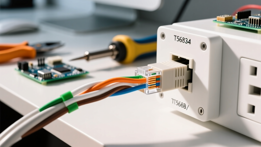
The Core Wiring Diagrams: T568A vs. T568B Compliance
While both the T568A and T568B wiring schemes create functional straight-through cables, the ANSI/TIA-568.2-D standard mandates strict consistency across a single network infrastructure. Mixing the two creates crossover cables, which modern Auto-MDIX switches can negotiate, but doing so violates structured cabling standards and causes nightmares for future troubleshooting.
T568A Pinout (Government & Residential Standard)
- Pin 1: White/Green
- Pin 2: Green
- Pin 3: White/Orange
- Pin 4: Blue
- Pin 5: White/Blue
- Pin 6: Orange
- Pin 7: White/Brown
- Pin 8: Brown
T568B Pinout (Commercial Standard)
- Pin 1: White/Orange
- Pin 2: Orange
- Pin 3: White/Green
- Pin 4: Blue
- Pin 5: White/Blue
- Pin 6: Green
- Pin 7: White/Brown
- Pin 8: Brown
Code Compliance Rule: T568A is generally required for US government contracts and is preferred in new residential builds due to its backward compatibility with USOC (Universal Service Order Code) 1-pair and 2-pair telephone wiring. T568B remains the dominant commercial standard. Document your chosen scheme on the electrical as-built drawings.
NEC Cable Ratings & Fire Safety Matrix
The physical wiring diagram is useless if the cable jacket violates fire codes. The NEC categorizes communications cables by their flammability and smoke production characteristics. Using a cheaper CM cable in a return-air plenum is a severe violation that fire marshals actively pursue.
| NEC Rating | Designation | Allowed Locations | Jacket Material & Safety Profile |
|---|---|---|---|
| CMP | Plenum | Ducts, plenums, environmental air-handling spaces | FEP or low-smoke PVC. Self-extinguishing, produces minimal toxic smoke. |
| CMR | Riser | Vertical shafts, floor-to-floor runs (non-plenum) | PVC with fire-retardant coating. Prevents flame spread from floor to floor. |
| CM | General Purpose | Single-floor commercial runs, surface mounting | Standard PVC. Will burn and emit toxic smoke; banned in plenums/risers. |
| CMX | Outdoor / Residential | Exterior building runs, single-family homes | Polyethylene (PE). UV resistant but highly flammable indoors. |
High-Voltage Separation Requirements
One of the most critical safety and performance aspects of a Cat5 wiring diagram is physical routing relative to high-voltage AC power. NEC Article 800.133(A)(2) and OSHA wiring safety standards dictate strict separation distances to prevent electromagnetic interference (EMI) and, more importantly, to prevent high-voltage faults from energizing the low-voltage data lines, which poses a lethal shock hazard to technicians.
Minimum Separation Distances (Parallel Runs)
- Under 2 kVA (e.g., standard 120V/20A circuits): Minimum 2 inches (50mm) separation.
- 2 kVA to 5 kVA (e.g., 208V/240V heavy appliances): Minimum 12 inches (300mm) separation.
- Over 5 kVA (e.g., industrial feeders): Minimum 24 inches (600mm) separation.
Routing Best Practice: If data and power lines must cross, they must intersect at a strict 90-degree angle to minimize inductive coupling and EMI.
PoE Thermal Compliance and Cable Bundling
With the rise of IoT sensors, Wi-Fi 6E access points, and security cameras, Power over Ethernet (PoE) is ubiquitous. While Cat5e supports IEEE 802.3at (PoE+, up to 30W), pushing wattage through 24 AWG copper generates significant heat. The BICSI Telecommunications Distribution Methods Manual (TDMM) and TIA TSB-184 guidelines explicitly warn against tight cable bundling.
The Hazard of the 'Velcro Strap Squeeze'
When more than 24 PoE-carrying Cat5 cables are bundled tightly together with zip ties or over-tightened Velcro straps, the center cables cannot dissipate heat. Internal cable temperatures can exceed 60°C (140°F), leading to:
- Acceleration of copper oxidation and insertion loss.
- Melting or softening of the HDPE pair insulation, altering the twist geometry.
- Increased DC resistance, causing voltage drops that reboot remote devices.
- In plenum spaces, excessive heat degrades the fire-retardant properties of the CMP jacket.
Code-Compliant Fix: Use loose hook-and-loop straps, maintain a 1-inch spacing between bundles in cable trays, and limit PoE+ bundles to 24 cables. If running 4-pair Cat6A for high-wattage PoE++ (802.3bt), bundling limits must be further reduced.
Physical Termination Limits: Bend Radius and Pull Tension
A perfectly mapped wiring diagram will still fail certification if the physical installation parameters are violated. The ANSI/TIA-568.2-D standard dictates strict mechanical limits to preserve the precise twist ratios of the copper pairs.
1. The 4x Bend Radius Rule
The minimum bend radius for a 4-pair UTP Cat5/Cat5e cable during and after installation is 4 times the outer diameter (OD) of the cable. For standard Cat5e (approx. 0.22 inches OD), the minimum bend radius is roughly 0.88 inches. Bending the cable tighter than this compresses the internal dielectric insulation, causing impedance mismatches and severe return loss failures.
2. Pulling Tension Limits
Never exceed 25 lbs (110 Newtons) of pulling tension on a Cat5/Cat5e cable. Exceeding this limit physically stretches the copper conductors and untwists the pairs inside the jacket. This destroys the cable's ability to reject Near-End Crosstalk (NEXT) and can snap the fragile 24 AWG copper cores.
3. The 0.5-Inch Untwist Limit
When terminating the cable into an RJ45 modular plug or a 110-style keystone jack, the pairs must remain twisted as close to the termination point as possible. The standard allows a maximum of 0.5 inches (13mm) of untwisted wire at the point of termination. Exceeding this creates an antenna effect, broadcasting EMI and failing compliance certification.
Summary of Common Inspector Failures
According to data aggregated by the National Fire Protection Association (NFPA) and local electrical boards, the following low-voltage infractions routinely trigger stop-work orders:
- Plenum Violations: Running CM or CMX rated cables above drop-ceiling tiles that act as return-air plenums.
- Improper Support: Using ceiling grid wires, sprinkler pipes, or HVAC ductwork to support data cables. NEC 300.11 requires independent, dedicated support structures (e.g., J-hooks or cable trays).
- Firestop Omissions: Failing to apply intumescent firestop putty or caulk where Cat5 cables penetrate fire-rated drywall or concrete floors between zones.
- Abandoned Cable: Leaving dead, un-terminated Cat5 cables in ceilings or walls. NEC 800.25 requires the removal of accessible abandoned communications cables to reduce fuel loads in a fire.
Mastering the wiring diagram for Cat5 cable is only 10% of the job. The remaining 90% relies on your adherence to NEC fire ratings, separation matrices, and physical installation tolerances. Always consult the latest local amendments to the NEC and BICSI guidelines before initiating any commercial or multi-family low-voltage infrastructure project.