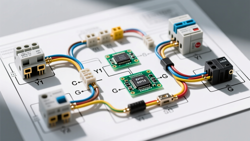

Why Schematics Beat Pictorials in HVAC Troubleshooting
When a residential split system fails in the middle of a July heatwave, guessing is not a diagnostic strategy. To accurately trace faults, technicians must rely on a proper wiring diagram for HVAC systems rather than a simple pictorial layout. While pictorial diagrams show the physical placement of components like the contactor, capacitor, and compressor, they fail to illustrate the logical sequence of operations. Schematics, on the other hand, use standardized ladder logic to map exactly how current flows through both the high-voltage (240V) and low-voltage (24VAC) control circuits.
As of 2026, with the industry fully transitioned to SEER2 efficiency standards and variable-speed inverter compressors becoming the norm in premium models like the Daikin Fit or Carrier Infinity series, understanding these schematics is more critical than ever. A miswired control circuit won't just cause a no-cool condition; it can instantly fry a $600 smart inverter control board.
Decoding the Ladder Logic: High vs. Low Voltage
Every standard HVAC schematic is divided into two distinct sections. Understanding the boundary between them is the first step to mastering the diagram.
1. The High-Voltage Circuit (Line Voltage)
This section handles the heavy lifting, typically 240VAC for the compressor and 120VAC for the condenser fan motor and air handler blower. On the schematic, this is represented by the outer rails of the ladder, usually labeled L1 and L2. Current flows from the main disconnect, through the contactor contacts, and into the compressor and fan motors. According to NFPA 70 (National Electrical Code) Article 440, these circuits require specific overcurrent protection and disconnect ratings based on the unit's MCA and MOPD data.
2. The Low-Voltage Circuit (Control Voltage)
This is the 'brain' of the operation, operating at a safe 24VAC stepped down from a transformer in the air handler. The ladder rails here are typically labeled R (Hot/Power) and C (Common). This circuit includes the thermostat, pressure switches, high-limit switches, and the contactor coil. If the unit has power but the contactor isn't pulling in, the fault almost always lies in this 24V ladder.
Step-by-Step Trace: A Call for Cooling
Let's trace a standard cooling call through the wiring diagram for HVAC systems to see how the logic flows:
- Thermostat Call: The thermostat closes the circuit between R (24VAC) and Y (Cooling).
- Air Handler Transit: The 24V signal travels via the Y wire to the indoor air handler control board, passing through the condensate overflow safety switch (a normally-closed switch that breaks the circuit if the drain pan is full).
- Outdoor Unit Arrival: The signal exits the air handler and enters the outdoor condenser on the Y terminal.
- Pressure Safeties: The Y circuit passes through the high-pressure and low-pressure switches. If refrigerant pressures are abnormal, these switches open, breaking the 24V path.
- Contactor Coil Energization: The 24V signal reaches the contactor coil. The other side of the coil is wired to the C (Common) terminal, completing the 24VAC circuit.
- High-Voltage Engagement: The magnetic field pulls the contactor plunger down, closing the L1 and L2 high-voltage contacts, sending 240V to the compressor and fan motor.
Wire Gauge, Breaker Sizing, and Disconnects
One of the most common code violations found during municipal inspections is improper wire sizing or over-fusing. Never guess the breaker size based on the tonnage alone. Always check the unit's data plate for the MCA (Minimum Circuit Ampacity) and MOPD (Maximum Overcurrent Protection Device). The US Department of Energy emphasizes proper electrical sizing to prevent fire hazards and ensure optimal equipment lifespan (DOE Central Air Conditioning Guide).
| System Tonnage | Typical MCA | Typical MOPD | Copper Wire Gauge (THHN/THWN) | Disconnect Switch Size |
|---|---|---|---|---|
| 1.5 Ton | 12A | 20A | 14 AWG | 30A |
| 2.0 Ton | 16A | 25A | 12 AWG | 30A |
| 3.0 Ton | 22A | 35A | 10 AWG | 60A |
| 4.0 Ton | 29A | 45A | 8 AWG | 60A |
| 5.0 Ton | 36A | 50A | 6 AWG | 60A |
Note: Aluminum wire requires upsizing by one gauge, but copper is the 2026 industry standard for HVAC branch circuits due to superior conductivity and termination reliability.
Real-World Failure Modes & Multimeter Diagnostics
Reading the diagram is only half the battle; applying it to live troubleshooting separates the parts-changers from the true technicians.
Scenario 1: Contactor Pulls In, Compressor Hums but Won't Start
The Diagram Tells Us: 240V is reaching the compressor, meaning the contactor and high-voltage wiring are intact. The issue is likely a lack of starting torque.
The Fix: Test the dual run capacitor (typically 45/5 MFD or 40/5 MFD). Use a multimeter with a capacitance setting. A healthy 45 MFD side should read within 6% tolerance (42.3 to 47.7 MFD). If it reads 30 MFD or shows physical bulging, the dielectric fluid has degraded. Replace it immediately to prevent the compressor from tripping its internal thermal overload.
Scenario 2: 24VAC Present at Contactor Coil, But Coil Doesn't Pull
The Diagram Tells Us: The control circuit is complete, but the mechanical action isn't happening.
The Fix: Disconnect power and measure the resistance (Ohms) across the contactor coil terminals. A standard 24VAC coil (like a Packard C240A) should read between 10 and 25 ohms. If your multimeter reads 'OL' (Open Line), the coil winding is broken internally. Replace the contactor.
Scenario 3: The Heat Pump Reversing Valve Trap
When wiring a heat pump thermostat, the O (Orange) and B (Blue) terminals dictate the reversing valve state. This is a massive edge case that trips up beginners. Most manufacturers (Carrier, Trane, Lennox) energize the reversing valve on a call for cooling (O terminal). However, Rheem and Ruud historically energize the valve on a call for heating. Always check the O/B setup menu on your smart thermostat; setting this backward will result in the system blowing cold air in the winter and hot air in the summer.
2026 Smart Thermostat Integration and the C-Wire
Modern Wi-Fi thermostats, such as the Ecobee Smart Thermostat Premium or the Nest Learning Thermostat (4th Gen), feature high-resolution touchscreens and continuous network connectivity. They require a dedicated C-Wire (Common) to provide continuous 24VAC power.
Pro Tip: Never rely on 'power stealing' from the Y or W circuits for a smart thermostat. Power stealing routes a trickle of current through the contactor coil or gas valve to keep the thermostat screen on. This can cause the outdoor contactor to rapidly chatter, or worse, inadvertently open a gas valve, creating a severe safety hazard.
Always run an 18/5 or 18/8 thermostat cable to ensure you have a dedicated R, C, Y, W, and G connection, future-proofing the control wiring.
Essential Safety Protocols: Lockout/Tagout
Working on HVAC systems involves lethal voltages and high-pressure refrigerants. The Occupational Safety and Health Administration (OSHA) mandates strict adherence to electrical safety practices. Before opening any condenser access panel or air handler blower compartment:
- Pull the outdoor disconnect block and lock it out.
- Turn off the indoor air handler breaker at the main panel.
- Use a CAT III or CAT IV rated multimeter to verify zero voltage across L1 and L2, and from L1/L2 to ground.
- Wait at least 5 minutes after pulling power before touching the run capacitor or inverter board terminals, as high-voltage DC capacitors in variable-speed units can retain lethal charges long after power is removed.
Mastering the wiring diagram for HVAC systems transforms a chaotic nest of colored wires into a logical, readable map. By understanding ladder logic, respecting MCA/MOPD ratings, and methodically tracing the 24V control sequence, you can diagnose and repair complex climate control systems with precision and safety.