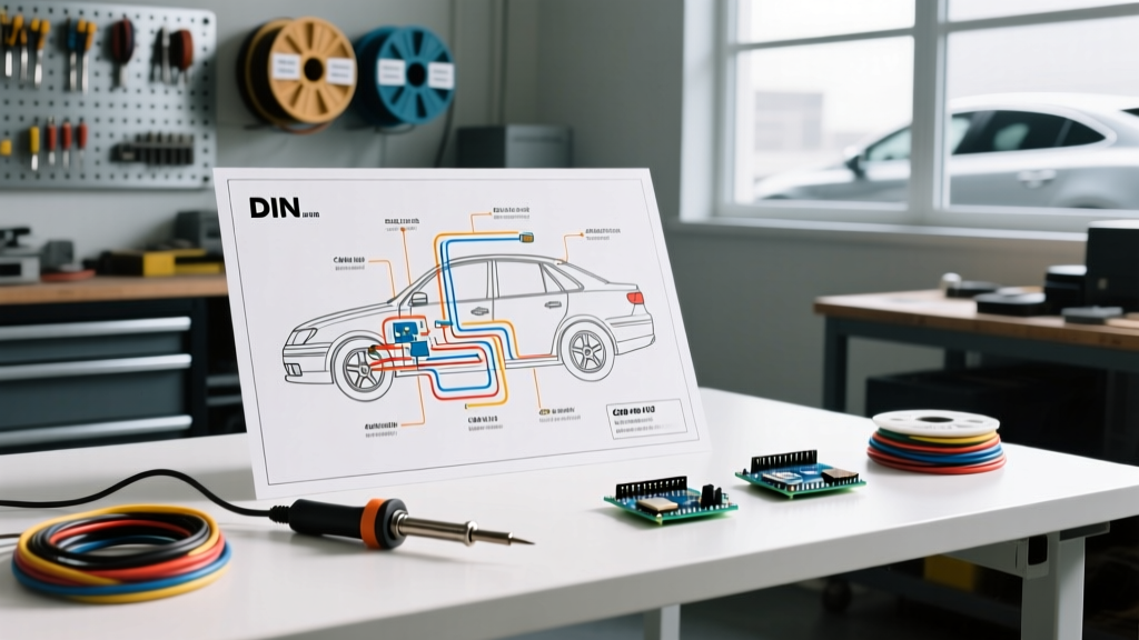

The Evolution of Automotive Schematics: From Point-to-Point to CAN-Bus
Tracking down an electrical gremlin in a modern vehicle requires more than just a test light and a guess. Whether you are restoring a 1969 Chevrolet C10 or diagnosing a parasitic draw on a 2022 Ford F-150, accessing accurate schematics is non-negotiable. Fortunately, the internet has democratized access to factory service manual (FSM) data. However, knowing where to find free wiring diagrams for vehicles is only the first step; understanding how to decode multiplexed networks, DIN terminal standards, and SAE wire gauge specifications is what separates a parts-changer from a true diagnostic technician.
Top Reliable Sources for Free Vehicle Wiring Diagrams
While paid subscriptions like Mitchell1 ProDemand or ALLDATA offer comprehensive, dealer-level schematics, several high-quality free alternatives exist for the DIYer and independent technician.
- AutoZone Repair Guides: By creating a free account on AutoZone's website and adding your specific vehicle to the "garage," you gain access to Chilton and Haynes-based wiring diagrams. These are excellent for point-to-point circuits (lighting, horns, basic starting systems) but often lack deep CAN-bus network topology.
- Manufacturer Enthusiast Forums: Communities like Ford-Trucks.com, LS1Tech, and Bimmerfest are goldmines. Users frequently upload PDF scans of official FSM wiring sections. Search the forum using the exact engine code and chassis year (e.g., "2018 F-150 5.0L Coyote PCM pinout PDF").
- BBB AutoLine & NHTSA Databases: While not traditional wiring diagrams, the National Highway Traffic Safety Administration (NHTSA) defects database is crucial. If you are tracing a melted harness or a recurring ground fault, checking NHTSA Technical Service Bulletins (TSBs) will reveal if the manufacturer has already issued a revised wiring schematic and harness repair kit.
- Open-Source EV Communities: For electric vehicles and hybrid conversions, GitHub repositories and sites like OpenInverter provide incredibly detailed, community-mapped high-voltage and low-voltage control schematics that OEMs usually keep proprietary.
Decoding the Schematic: Standard Automotive Symbols & DIN 72552
European and Asian manufacturers heavily rely on the DIN 72552 standard for terminal numbering. If your free wiring diagram uses numbers instead of descriptive text on relays and ignition switches, you must memorize these designations to avoid catastrophic short circuits.
| DIN Terminal | Function / Description | Common Application |
|---|---|---|
| 30 | Direct Battery Power (Hot at all times) | Main power feed to relay or fuse box |
| 15 | Ignition Switched Power (Hot in Run/Start) | ECU power, radio, dashboard accessories |
| 50 | Starter Motor Control (Hot only in Crank) | Starter solenoid trigger wire |
| 31 | Ground / Earth Return | Chassis ground, battery negative |
| 85 / 86 | Relay Coil Terminals (Polarity usually irrelevant) | Control side of an ISO 7588 standard relay |
| 87 | Normally Open (NO) Relay Output | Power to fuel pump, cooling fan, or horn |
| 87a | Normally Closed (NC) Relay Output | Security system interrupts, alarm horn |
Step-by-Step: Tracing a Parasitic Draw Using a Free Diagram
Modern vehicles (2015 and newer) utilize multiplexed CAN-bus (Controller Area Network) systems. When you turn the key off, modules do not shut down instantly; they enter a "sleep mode." Testing a parasitic draw immediately after shutting off the engine will yield false readings of 2A to 4A. Here is the exact procedure used by master technicians.
1. Prepare the Vehicle for Sleep Mode
Close all doors, latch the hood, and remove the key fob at least 20 feet away from the vehicle (to prevent passive keyless entry wake-ups). Wait a minimum of 30 to 45 minutes. Modules like the Body Control Module (BCM) and telematics units take this long to power down to their baseline quiescent state.
2. Setup the Multimeter with a Shunt
Use a high-quality DMM like the Fluke 87V (approx. $450) or the Innova 3340 (approx. $35). Set the meter to the 10A port. Critical Step: Connect a 10A fused jumper wire in parallel with your multimeter probes before disconnecting the negative battery terminal. This prevents the initial capacitive surge from blowing your multimeter's internal fuse when you make the final connection.
3. Measure and Isolate
Remove the shunt jumper wire and read the meter. The acceptable parasitic draw for a modern CAN-bus vehicle is typically between 20mA and 50mA (0.02A - 0.05A). Heavy-duty trucks with aftermarket telematics may draw up to 80mA. If your reading is 1.5A, begin pulling fuses one by one while referencing your free wiring diagram to see which circuit drops the amperage. If pulling the "Radio/Audio" fuse drops the draw to 30mA, your diagram will show you that the amplifier or head unit is failing to receive the CAN-bus "sleep" signal on the network wire.
Understanding SAE Wire Gauge Standards in Diagrams
Free wiring diagrams often list wire sizes in AWG (American Wire Gauge) or metric cross-sectional area (mm²). According to SAE International standards (specifically SAE J1128 for low-tension primary cable), sizing is critical to prevent voltage drop and harness fires. When adding aftermarket accessories based on a diagram's spare circuit capacity, adhere to these limits:
- 18 AWG (0.8mm²): Max 5A-8A. Used for LED lighting, low-draw sensors, and CAN-bus data lines.
- 14 AWG (2.0mm²): Max 15A. Standard for interior accessories, fuel pumps, and power windows.
- 10 AWG (5.0mm²): Max 30A. Required for high-draw cooling fans, off-road lighting relays, and trailer brake controllers.
- 4 AWG (20mm²): Max 60A-80A. Used for main battery-to-fuse-box feeds, high-output alternator upgrades, and winch power lines.
Edge Cases: When Free Diagrams Fail You
The biggest limitation of free, aftermarket-sourced wiring diagrams is their handling of Multiplexing and LIN-bus (Local Interconnect Network) circuits. In older vehicles, a wire from a switch to a motor carried a steady 12V when activated. In modern vehicles, a steering wheel button sends a digital data packet over a single wire to a clock spring, which then transmits it via CAN-bus to the BCM, which finally triggers a solid-state relay to roll down the window.
If your free diagram shows a "Data Link" or "Network" line connecting multiple modules, a standard digital multimeter is virtually useless for diagnosing it. A DMM will only show an average voltage (usually around 2.5V for CAN-High and 2.4V for CAN-Low). To properly diagnose network faults, shorts, or corrupted packets, you must upgrade your tooling to an automotive oscilloscope, such as the PicoScope 4225A (approx. $1,200), to visually verify the square-wave voltage transitions.
Frequently Asked Questions
Can I use a wiring diagram from a similar year model?
Automakers frequently implement mid-year running changes. A 2017 diagram might show a ground point at G204, while a late-build 2017 model might have moved it to G205 due to a factory TSB. Always verify the build date on your driver's side door jamb sticker and match it to the diagram's effective date.
Why does my diagram show a diode symbol on a relay circuit?
Many modern vehicles use solid-state relays or place flyback diodes across standard relay coils to suppress voltage spikes (inductive kickback) when the coil is de-energized. If you are bypassing or repairing this circuit, failing to respect the diode's polarity will instantly destroy the BCM driver transistor.