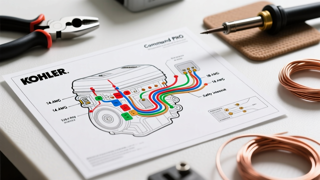

Introduction to Kohler Electrical Architecture
Interpreting a wiring diagram for Kohler engine systems requires more than just tracing lines from point A to point B. Whether you are servicing a commercial zero-turn mower equipped with a Command PRO CV680 twin-cylinder or a residential generator running a Courage single-cylinder, the electrical harness is the nervous system of the machine. In 2026, with the widespread adoption of Kohler’s Electronic Fuel Injection (EFI) and Module Digital Ignition (MDI) systems, the complexity of these diagrams has increased significantly compared to the simple magneto-kill circuits of the early 2000s.
Misinterpreting a Kohler schematic often leads to catastrophic ECU failure, burned stators, or bypassed safety interlocks. This guide provides a deep-dive reference into Kohler’s standard color codes, circuit logic, and diagnostic procedures, ensuring you can confidently navigate any OEM schematic.
Kohler Command PRO Wire Color & Gauge Matrix
While aftermarket harnesses may deviate, factory Kohler wiring diagrams adhere to a strict color-coding and gauge standard. Using the correct American Wire Gauge (AWG) is critical; undersizing wires for high-draw components like the PTO clutch or starter solenoid will cause severe voltage drops and component burnout. According to Southwire Electrical Calculator data, even a 10-foot run of 18 AWG wire carrying 4 amps will result in a voltage drop that can starve an electromagnetic PTO clutch.
| Circuit Function | Standard Wire Color | AWG Size | Amperage & Technical Notes |
|---|---|---|---|
| Starter Motor Feed | Red | 10 AWG | 150A+ surge; Requires heavy-duty ring terminals. |
| Ignition Switch to Solenoid | Purple | 14 AWG | 5A-10A; Carries the 12V trigger signal to the starter relay. |
| Stator AC Output | Yellow (x2 or x3) | 14 AWG | 28-35V AC per leg at 3600 RPM; High heat environment. |
| Rectifier DC Output | Red | 12 AWG | 15A-25A DC; Must be fused within 6 inches of the battery. |
| PTO Clutch Feed | Orange or Blue | 14 AWG | 3.5A-4.5A continuous; Dedicated 10A relay required. |
| Sensors & Safety Switches | Green / Black | 18 AWG | Under 1A; Used for seat, brake, and PTO interlock logic. |
Decoding the Ignition and Charging Circuits
The most common area of confusion when reading a Kohler schematic is distinguishing between traditional magneto ignition systems and modern digital modules.
Traditional Magneto vs. MDI (Module Digital Ignition)
On older Kohler Courage and early Command models, the ignition coil is a simple magneto. The wiring diagram will show a single 'kill wire' (usually white or black) routed from the coil to the ignition switch. When the key is turned off, the switch grounds this wire, shorting the primary coil winding and stopping the spark.
However, modern Command PRO engines utilize MDI (Module Digital Ignition). If you look at a 2026 Kohler EFI or advanced carburetor wiring diagram, you will not find a ground-to-kill wire. Instead, the MDI module requires a constant 12V positive feed to operate. The safety interlock system interrupts this 12V feed to kill the engine. Connecting a ground wire to an MDI harness will instantly destroy the $180 ignition module.
The 3-Phase Stator and Bridge Rectifier Path
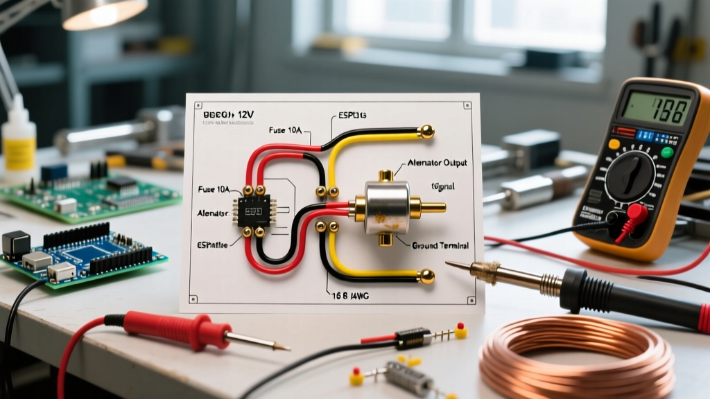
Kohler’s charging system relies on a 3-phase (or dual-phase) stator located beneath the flywheel. The wiring diagram will show two or three yellow wires exiting the stator and entering the bridge rectifier/voltage regulator.
- AC Side: The stator generates raw Alternating Current (AC). At 3600 RPM, each yellow leg should output between 28V and 35V AC.
- DC Side: The rectifier converts this AC into Direct Current (DC) and regulates it down to a safe 13.8V–14.4V DC to charge the battery and run accessories.
- Grounding: The rectifier case must be grounded to the engine block. A missing ground strap will cause the rectifier to overheat and fail within minutes.
Safety Interlock Logic: SAM and Relay Systems
Kohler commercial mowers utilize a complex safety interlock network to comply with NFPA and OSHA operational safety guidelines. The wiring diagram will typically feature a SAM (Safety Arrest Module) or a network of discrete relays.
- Seat Switch (Normally Open/Closed): Detects operator presence. If the operator leaves the seat while the PTO is engaged, the SAM module cuts the 12V feed to the MDI or grounds the magneto kill wire.
- Brake Switch: The engine will only crank if the parking brake is fully engaged. This is wired in series with the starter solenoid trigger circuit.
- PTO Switch: Acts as a permissive switch. If the PTO is engaged during cranking, the starter circuit is interrupted to prevent the blades from spinning upon startup.
Expert Tip: When troubleshooting a 'no-crank' condition on a Kohler Command PRO, do not immediately replace the starter solenoid. Use a multimeter to back-probe the purple trigger wire at the solenoid while turning the key. If you read 12V, the solenoid is bad. If you read 0V, the fault lies upstream in the brake switch, PTO switch, or ignition switch.
Step-by-Step Multimeter Diagnostics for Kohler Harnesses
When the wiring diagram indicates a charging failure, follow this exact diagnostic sequence to isolate the fault without throwing expensive parts at the engine.
Step 1: The Stator AC Output Test
Disconnect the main engine harness plug to isolate the stator from the rectifier and the rest of the mower's wiring. Set your digital multimeter to VAC (Volts AC). Start the engine and run it at full throttle (3600 RPM). Probe the yellow wires in the engine-side connector. You should read 28V to 35V AC between the yellow legs. If the voltage is below 20V AC, the stator is burned out, or the flywheel key has sheared, altering the magnetic timing.
Step 2: The Rectifier DC Output Test
Reconnect the harness. Set your multimeter to VDC (Volts DC). With the engine running at 3600 RPM, probe the red DC output wire at the rectifier and the engine block ground. You should read 13.8V to 14.4V DC. Edge Case: If you read battery voltage (12.6V) but it does not rise with RPM, the rectifier is dead. If you read AC voltage on this DC test, one or more diodes inside the rectifier bridge have shorted, allowing raw AC to reach the battery, which will boil the battery acid and destroy the ECU on EFI models.
Common Wiring Harness Failure Modes in 2026
Based on field service data and Kohler Engines Technical Support bulletins, the following are the most frequent electrical failures encountered by technicians:
- EFI Fuel Pump Voltage Starvation: Kohler Command PRO EFI systems use a high-pressure fuel pump drawing up to 3A. If the wiring harness is routed too close to the exhaust manifold, the 14 AWG wire insulation melts, causing a short. Always use high-temp fiberglass sleeving over EFI harness branches.
- Rectifier Connector Corrosion: The 3-pin AMP connector between the stator and rectifier is highly susceptible to water intrusion from pressure washing. Corrosion increases resistance, generating enough heat to melt the plastic connector housing. Applying dielectric grease during reassembly is mandatory.
- Hour Meter Parasitic Draw: Many aftermarket wiring diagrams route the hour meter directly to the 12V battery bus. Over a 3-month winter storage period, this 15mA parasitic draw will completely sulfate a standard U1 lawn tractor battery. Always wire the hour meter through the ignition switch's 'accessory' or 'run' terminal.
Mastering the wiring diagram for Kohler engine platforms is about understanding the logic behind the circuits, not just the physical routing. By respecting wire gauge requirements, understanding the shift from ground-kill to power-enable ignition modules, and systematically testing the stator-to-rectifier path, you can diagnose and repair Kohler electrical systems with absolute precision.