
The Helm Panel Connection: Why Fuel Gauges Fail at the Breaker
When a marine fuel gauge reads empty, full, or fluctuates erratically, most boaters immediately suspect the tank sender. However, as marine electrical systems grow more complex, the root cause frequently lies at the helm DC breaker panel. A proper wiring diagram for boat fuel gauge integration requires more than just connecting three wires; it demands strict adherence to voltage drop limits, ABYC overcurrent protection standards, and precise bus bar terminations. In 2026, with the proliferation of sensitive digital dash displays and LED-backlit analog gauges, ensuring clean, protected power from your main distribution panel to the instrument cluster is critical.
This guide approaches the fuel gauge circuit from the perspective of the Panel & Breaker Guide, focusing on how to properly fuse, route, and terminate the wiring harness at the helm to ensure reliable fuel level monitoring.
Matching the Sender: The Hidden Variable in Your Wiring Diagram
Before terminating any wires at your breaker panel, you must verify the resistance range of your fuel tank sender. The gauge and the sender must operate on the exact same ohm scale. If you are upgrading an older vessel's panel and installing a modern Faria or Sierra gauge, a mismatch will result in a gauge that pegs to full or empty immediately upon energizing the breaker.
| Standard | Empty Resistance (Ohms) | Full Resistance (Ohms) | Common Regions / Brands |
|---|---|---|---|
| US Standard | 240 Ω | 33 Ω | North America, Faria, Sierra, VDO (US) |
| EU Standard | 10 Ω | 180 Ω | Europe, Wema EU, VDO (EU) |
| Japanese Standard | 110 Ω | 3 Ω | Yamaha, Suzuki, Honda outboards |
Source: Resistance specifications verified via Wema USA marine sensor documentation.
Core Wiring Diagram for Boat Fuel Gauge: Pinout & Panel Routing
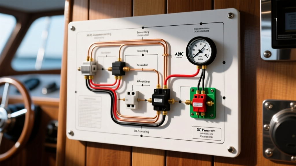
A standard analog or digital marine fuel gauge utilizes a 3-terminal or 4-terminal setup (the 4th being for the illumination ground). Below is the definitive wiring flow from the DC breaker panel to the gauge and down to the tank.
1. The Ignition Feed (Power)
Power originates at the battery switch, travels to the main DC distribution panel, and passes through a dedicated breaker. From the breaker's load side, an Ignition (I) wire (typically purple in standard marine harnesses) routes to the helm and connects to the I terminal on the back of the fuel gauge. This ensures the gauge only draws power when the key switch is in the 'Run' or 'Accessory' position.
2. The Signal Wire (Sender to Gauge)
The S terminal on the gauge connects via a signal wire (often pink with a purple stripe) directly to the S terminal on the fuel tank sender. Crucial Panel Routing Note: This wire carries a low-voltage, variable-resistance analog signal. It must be routed through the helm panel's wiring chase at least 6 inches away from high-tension ignition cables, alternator output wires, and VHF coax to prevent Electromagnetic Interference (EMI), which causes erratic needle dancing.
3. The Ground (Negative Return)
The G terminal on the gauge must connect to a dedicated, clean negative bus bar behind the helm panel. Do not rely on the metal dash casing or the gauge's mounting bracket for a ground return. A 16 AWG black wire should route from the gauge's G terminal directly to the helm's negative bus bar, which ultimately ties back to the main DC negative bus near the battery bank.
Expert Insight: Never share the fuel sender's ground wire with high-draw devices like bilge pumps or livewell aerators. Voltage spikes from inductive loads kicking off will backfeed through the negative bus, causing the fuel gauge needle to spike or drop momentarily.
Breaker Panel Integration: ABYC E-11 Compliance and Sizing
According to the American Boat & Yacht Council (ABYC) E-11 standards, overcurrent protection devices (breakers or fuses) are designed to protect the wire, not the appliance. However, instrument panels require a nuanced approach to breaker sizing.
Calculating the Correct Breaker Size
A standard analog fuel gauge draws approximately 0.15A for the movement coil and up to 1.2A if using incandescent backlighting. Modern 2026 LED-lit gauges draw less than 0.05A for illumination. If you run 16 AWG marine-grade tinned copper wire from a Blue Sea Systems ST Blade fuse block to the helm, the wire is rated for roughly 10A to 13A.
If you install a 10A breaker to protect the 16 AWG wire, a short circuit inside the delicate gauge PCB or coil could cause a fire before the 10A breaker trips. Best Practice: Use a dedicated 3A or 5A ATC/ATO blade fuse or a 5A toggle circuit breaker for the instrumentation bus. This protects the 16 AWG wire while ensuring the low-draw gauge is protected from internal faults.
Wire Gauge Selection and Voltage Drop
While 16 AWG is standard for gauge lighting and signal, the distance from the breaker panel to the helm, and from the helm to the aft fuel tank, dictates voltage drop. The ABYC recommends a maximum 3% voltage drop for non-critical circuits, but instrument panels benefit from tighter tolerances.
| Total Circuit Length (One Way) | Recommended Wire Gauge (AWG) | Voltage Drop @ 2A (Approx) |
|---|---|---|
| Up to 15 Feet | 16 AWG | < 1.5% |
| 16 to 25 Feet | 14 AWG | < 2.0% |
| 26 to 40 Feet | 12 AWG | < 2.5% |
Note: Always use marine-grade, tinned copper wire (e.g., Ancor or Genuinedealz) to prevent galvanic corrosion inside the breaker panel terminals.
Step-by-Step Panel Termination and Routing
- De-energize the Panel: Disconnect the negative battery cable before working on the DC breaker panel.
- Install the Breaker/Fuse: Mount a 5A breaker on the positive bus bar of your helm distribution panel.
- Crimp and Heat Shrink: Use adhesive-lined marine heat shrink ring terminals (3/16" or #10 stud size) for all panel connections. Avoid vinyl-insulated crimp connectors, which trap moisture and cause green corrosion at the bus bar.
- Route the Harness: Pass the 3-wire harness through the panel's dedicated wire chase. Secure with UV-resistant cable ties every 18 inches.
- Terminate at the Gauge: Use insulated female spade connectors (0.250") for the gauge terminals. Apply a dab of dielectric grease to prevent salt-air oxidation.
Troubleshooting Common Gauge & Breaker Failures
When your fuel gauge misbehaves, use this diagnostic matrix to isolate whether the fault lies at the breaker panel, the wiring harness, or the tank sender.
- Gauge Pegged to FULL: The signal wire (S terminal) is shorted to ground somewhere between the helm panel and the tank sender. Check for pinched wires in the bilge or behind the dash.
- Gauge Pegged to EMPTY: The signal wire is broken (open circuit), or the tank sender's float arm is stuck. Use a multimeter at the helm panel to measure resistance between the S wire and ground. If it reads infinite (OL), the wire is broken or the sender is dead.
- Gauge Reads Erratically: Usually caused by a poor ground connection at the helm's negative bus bar, or the signal wire is routed too close to the engine's high-tension ignition wires, introducing EMI noise.
- Breaker Trips Immediately: A dead short exists in the ignition (I) feed wire between the breaker panel and the back of the gauge. Inspect for crushed wires behind the dash panel.
Upgrading to Digital NMEA 2000 Fuel Sensors
For modern 2026 vessel refits, many boaters are abandoning analog variable-resistance senders in favor of digital NMEA 2000 fluid level sensors (such as the Garmin GFL 10 or Maretron TLA200). These digital sensors connect directly to the NMEA 2000 backbone via a Micro-C drop cable, entirely bypassing the analog signal wire. However, they still require clean 12V power and ground. When integrating these into your DC breaker panel, they should be fused on the same dedicated 5A 'Instrumentation' bus as your digital multi-function displays to ensure synchronized power cycling and prevent ground loops.
Frequently Asked Questions (FAQ)
Can I wire multiple fuel gauges to a single tank sender?
Yes, you can wire a gauge at the helm and a secondary gauge at a lower station or flybridge to the same sender. However, wiring them in parallel slightly alters the total circuit resistance, which can cause a 5% to 10% reading discrepancy. For dual-station accuracy, use a digital NMEA 2000 sender or a dedicated dual-station analog gauge kit.
Why does my fuel gauge drop when I start the engine?
This is a classic symptom of voltage drop at the breaker panel or the ignition switch. When the starter motor engages, it draws hundreds of amps, causing system voltage to plummet. If your helm breaker panel is fed by undersized main feeder cables, the voltage drop will starve the fuel gauge. Ensure your main panel feeders are sized correctly per USCG and ABYC guidelines.
Should the fuel gauge illumination wire be on the same breaker?
Best practice is to separate the gauge power (Ignition feed) from the illumination feed. Wire the illumination terminal to a dedicated 'Navigation Lights' or 'Panel Dimmer' circuit on your breaker panel. This allows you to control dash brightness independently of the engine's ignition state.