
The Anatomy of an Automotive Wiring Schematic
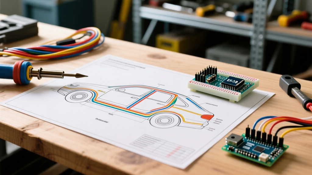
Staring at a factory service manual for the first time can feel like trying to decipher an ancient dialect. Modern vehicles contain over two miles of wiring, managed by dozens of interconnected modules. Learning how to read automotive electrical wiring diagrams is the single most valuable skill an automotive DIYer or technician can develop. It transforms guesswork into a systematic, logical diagnostic process.
In this step-by-step walkthrough, we will decode the universal symbols, trace a real-world high-current circuit, and apply 2026 diagnostic standards to isolate faults without throwing unnecessary parts at the vehicle. Whether you are working on a classic carbureted truck or a 2026 mild-hybrid with a 48V architecture, the foundational logic of power distribution remains identical.
DIN 72552 Terminal Codes: The Universal Language
Before tracing a single wire, you must understand the nomenclature. Most global automotive manufacturers use the German DIN 72552 standard to label electrical terminals. If you see a number inside a circle or next to a component pin on a schematic, it is likely a DIN code. Memorizing these eliminates the need to constantly reference the legend.
| DIN Code | Terminal Designation | Common Application |
|---|---|---|
| 30 | Direct Battery Power (Hot at all times) | Main fuse box feeds, constant memory modules |
| 15 | Ignition Switched Power | ECU wake-up, radio, HVAC blower motor |
| 31 | Ground (Return to Battery Negative) | Chassis grounds, sensor reference grounds |
| 50 | Starter Control Circuit | Ignition switch to starter solenoid |
| 85 / 86 | Relay Coil (Control Side) | PCM ground trigger, ignition switch feed |
| 87 / 87a | Relay Contact (Load Side) | 87 is Normally Open (NO), 87a is Normally Closed (NC) |
Wire Gauge and Color Coding Standards
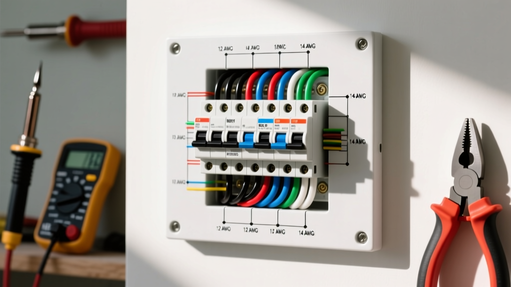
Automotive schematics denote wire size and color directly on the line. In North America, wire size is typically listed in AWG (American Wire Gauge), while European and Asian diagrams use metric cross-sectional area (mm²). A common point of confusion is converting between the two. For instance, a standard 18 AWG sensor wire is equivalent to 0.75 mm², while a heavy 10 AWG fuel pump feed wire equates to 5.0 mm².
Wire colors are abbreviated using two letters. A solid red wire is RD. A black wire with a white tracer stripe is BK/WT. Always trust the tracer color as the secondary identifier. In modern 2026 harnesses, manufacturers often use identical base colors for entirely different circuits, making the tracer stripe and the circuit number printed on the schematic your only reliable identifiers.
Step-by-Step Walkthrough: Tracing a Modern Fuel Pump Circuit
Let us apply this knowledge to a practical scenario. Your engine cranks but will not start. You suspect the fuel pump. Instead of dropping the tank immediately, we will use the wiring diagram to verify the circuit from the battery to the pump motor.
Step 1: Identify the Power Source and Protection
Locate the fuel pump motor symbol on the diagram (usually depicted as a circle with an 'M' and a pump impeller icon). Follow the wire upward to find its power source. You will trace a heavy-gauge wire (typically 12 AWG / 3.0 mm²) from the pump to a Fuel Pump Relay, and then to a specific fuse (e.g., Fuse F42, 20A) in the under-hood Power Distribution Center (PDC). The line connecting the fuse to the battery will be labeled 30, indicating it has constant battery voltage.
Diagnostic Action: Use a multimeter to check for 12.6V at both test points on top of the fuse. If voltage is present on the battery side but missing on the load side, the fuse is blown. If the fuse is blown, do not just replace it; a blown fuse indicates a short to ground downstream. You must find the chafed wire before installing a new fuse.
Step 2: Trace the Control Side (Low Current)
The relay acts as a heavy-duty remote switch. It has two distinct circuits: the low-current control side (pins 85 and 86) and the high-current load side (pins 30 and 87). Look at pins 85 and 86 on your diagram. One will receive ignition-switched power (DIN 15), and the other will route to the Powertrain Control Module (PCM). The PCM completes the circuit by providing a switched ground.
Diagnostic Action: With the key in the 'ON' position, use a test light or multimeter to verify 12V at pin 86. According to Fluke's automotive testing guidelines, you can also measure the resistance across the relay coil (pins 85 and 86). A healthy 12V automotive relay coil typically reads between 50 and 90 ohms. An open reading (OL) means the internal coil is broken.
Step 3: Trace the Load Side (High Current)
When the PCM grounds pin 85, the electromagnet pulls the internal switch closed, connecting pin 30 (Battery Power) to pin 87 (Feed to Fuel Pump). Follow the wire from pin 87 down to the fuel pump motor. Note any intermediate connectors, such as an inertia shut-off switch or a chassis ground splice.
Diagnostic Action: If the relay clicks but the pump does not run, the fault is on the load side. Back-probe the connector at the fuel pump with the circuit active. If you read 12V at the connector but the pump is dead, the pump motor is faulty. If you read 0V, you have an open circuit (broken wire or corroded connector) between the relay and the tank.
Step 4: Verify the Ground (The Forgotten Half)
Every circuit must return to the battery. The fuel pump ground wire will route to a chassis ground point, often labeled G104 or similar, which ultimately ties back to the battery negative (DIN 31). Corroded ground points are responsible for over 40% of all misdiagnosed electrical faults.
Advanced Diagnostics: Voltage Drop Testing
In 2026, throwing parts at a vehicle based on a simple continuity test is obsolete. Continuity tests only verify that a wire is unbroken; they do not verify that the wire can carry current under load. A wire composed of only two strands of copper will show continuity on a multimeter but will fail to run a 15-amp fuel pump.
This is where voltage drop testing becomes mandatory. As the National Institute for Automotive Service Excellence (ASE) and Fluke emphasize, voltage drop measures the exact amount of electrical pressure (voltage) lost as current pushes through resistance in a circuit.
The Golden Rule of Voltage Drop: In a 12V system, the total acceptable voltage drop across all switches, connectors, and wires on the power side should not exceed 0.5V. On the ground side, it should not exceed 0.1V to 0.2V. Anything higher indicates excessive resistance.
How to Perform a Ground-Side Voltage Drop Test
- Set your multimeter to DC Volts (mV scale for precision).
- Activate the circuit. The fuel pump must be running (or cranking) to push current through the wire.
- Place the red probe on the battery negative terminal (not the chassis, the actual lead post).
- Place the black probe on the ground wire at the fuel pump connector.
- Read the display. If you read 2.4V, you are losing 2.4 volts of electrical pressure to resistance in the ground wire. The pump is only receiving 9.6V, explaining why it runs weakly or not at all.
2026 Edge Cases: 48V Systems and CAN Bus Interference
As the automotive industry shifts toward 48V mild-hybrid architectures and high-speed CAN-FD (Flexible Data-rate) networks, reading wiring diagrams requires new safety protocols and diagnostic perspectives.
High-Voltage vs. Low-Voltage Isolation
On modern schematics, 48V and high-voltage hybrid lines are explicitly isolated from the standard 12V chassis ground. These wires are almost universally color-coded Orange or Red with Yellow striping and feature interlock loops (HVIL). When reading these diagrams, look for the 'isolation boundary' dashed lines. Never back-probe a 48V+ circuit with standard steel piercing probes; you must use CAT III or CAT IV rated non-contact voltage detectors and insulated multimeter leads to prevent arc flashes and personal injury.
CAN Bus Termination and Signal Diagrams
Unlike power circuits, Controller Area Network (CAN) diagrams do not show power flow; they show data topology. You will see two wires: CAN-High and CAN-Low, twisting together and terminating at two 120-ohm resistors. When diagnosing a 'U-code' (Network Communication code) using a diagram, you are looking for the physical location of these terminating resistors—usually inside the PCM and the instrument cluster. A total bus resistance of 60 ohms (two 120-ohm resistors in parallel) confirms the physical wiring topology is intact.
Summary: The Professional Diagnostic Workflow
Mastering how to read automotive electrical wiring diagrams is about adopting a rigid, logical workflow. By memorizing DIN terminal codes, understanding the separation of control and load circuits, and utilizing voltage drop testing instead of simple continuity checks, you elevate your diagnostics from guesswork to precision science. Always consult the factory service information (such as ALLDATA or Mitchell1 ProDemand) for your specific year, make, and model, as wire colors and pinouts vary wildly even between adjacent model years. Armed with the schematic and a quality digital multimeter, there is no electrical ghost in the machine you cannot track down.