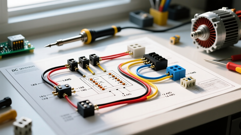

The Hidden Complexity of Automotive DC Motor Loads
While lighting and sensor circuits dominate modern vehicle schematics, inductive DC motor loads—such as radiator cooling fans, windshield wipers, and HVAC blowers—present unique wiring challenges. When interpreting auto electrical wiring diagrams, technicians often make the critical mistake of treating a motor like a simple resistive load. In reality, a motor is an electromagnetic device that generates massive inrush currents, back-EMF (electromotive force), and voltage spikes. As we navigate the increasingly complex electrical architectures of 2026, including 48V mild-hybrid auxiliary systems, mastering the 12V DC motor circuit remains a foundational diagnostic skill.
This tutorial dissects the symbology, load calculations, and real-world failure modes found in automotive motor wiring diagrams, using a high-draw cooling fan circuit as our primary case study.
Decoding Symbology: ISO vs. OEM Motor Schematics
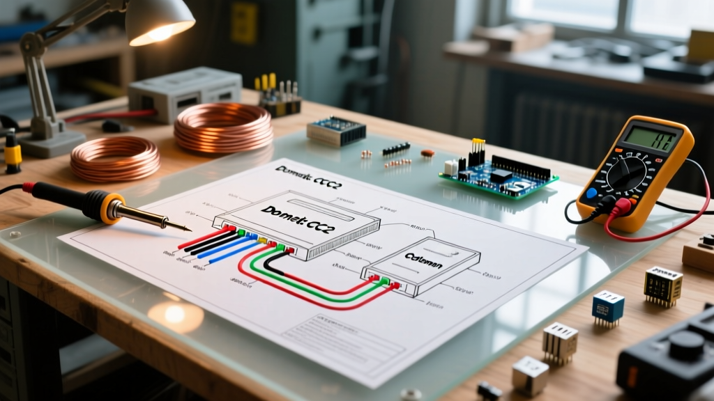
Before routing a single wire, you must understand how the diagram represents the physical components. Most modern auto electrical wiring diagrams adhere to ISO 2575 or DIN 72552 standards, though OEMs like Ford, GM, and Toyota often use proprietary variations.
| Component | Standard ISO Symbol | OEM Variation (Common) | Diagnostic Significance |
|---|---|---|---|
| DC Motor | Circle with 'M' or two overlapping circles | Rectangle with 'M' and polarity markers (+/-) | Overlapping circles denote armature and stator fields; crucial for identifying series vs. shunt wound wiper motors. |
| Relay Coil | Rectangle with diagonal line | Box with pins labeled 85/86 | Identifies the low-current trigger side. Reversing 85/86 on a diode-suppressed relay will short the ECU driver. |
| Thermal Switch | Circle with bimetallic arc | Square with 'TEMP' and resistance curve | Determines if the fan switch is Normally Open (NO) or Normally Closed (NC) for fail-safe operation. |
| Flyback Diode | Triangle with line parallel to coil | Often omitted in basic diagrams | If missing on the diagram, you must manually add one across pins 85/86 to protect solid-state ECU triggers. |
Tutorial: Wiring a High-Draw Cooling Fan Circuit
Let’s apply these diagrams to a real-world scenario: wiring a high-performance dual radiator cooling fan setup, such as the popular Spal VA01-AP10/C-39A 11-inch fans. Each motor draws roughly 11 Amps continuously at 14.4V, but the wiring diagram must account for the physical realities of inductive loads.
Phase 1: Load Calculation and Wire Sizing
A common error when reading auto electrical wiring diagrams is sizing the wire strictly for the continuous amperage listed on the motor spec sheet. An 11A motor does not pull 11A at startup. The stall current (inrush) can be 4 to 6 times higher, briefly hitting 50A+ for 200 milliseconds as the magnetic fields establish and the armature overcomes static friction.
Pro-Tip: SAE J1128 GXL Wire Standard
Never use standard PVC wire in an engine bay. Engine bay ambient temperatures routinely exceed PVC’s 105°C rating, leading to brittle insulation and short circuits. Always specify GXL (cross-linked polyethylene) wire, rated for 125°C. In 2026, 10 AWG GXL wire costs approximately $0.45 per foot, a negligible premium over PVC ($0.25/ft) for vastly superior thermal and abrasion resistance.
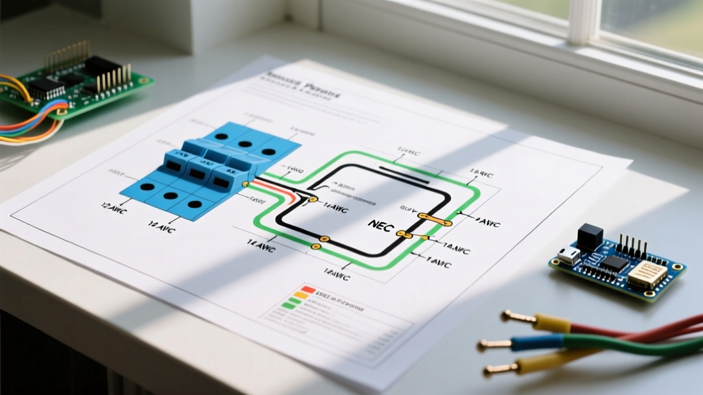
Wire Sizing Matrix for 12V Automotive Motors (15ft Round-Trip Run):
| Motor Continuous Draw | Estimated Inrush (Stall) | Recommended Wire Gauge (GXL) | Recommended Fuse Type & Rating |
|---|---|---|---|
| 5A - 10A (Blower Motor) | 25A - 40A | 12 AWG | 15A Time-Delay ATO |
| 10A - 15A (Single Cooling Fan) | 40A - 60A | 10 AWG | 25A MAXI or Slow-Blow ATO |
| 20A - 30A (Dual Fans / Winch) | 80A - 120A | 6 AWG or 4 AWG | 40A - 50A MAXI |
Phase 2: Relay Selection and Pinout Routing
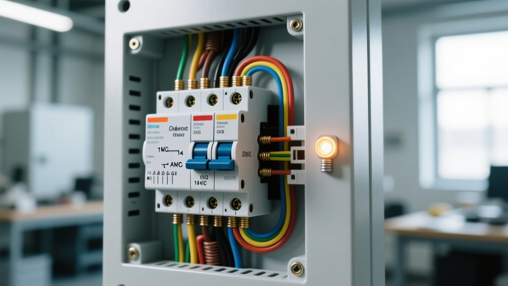
Most auto electrical wiring diagrams for cooling fans utilize a standard Bosch-style Mini-ISO 4-pin relay (e.g., Bosch Part # 0332014150, retailing around $7-$9). The diagram will route power as follows:
- Pin 30 (Power In): Fused 12V+ directly from the battery. Use an 8 AWG pigtail to the main fuse block.
- Pin 87 (Load Out): 10 AWG GXL wire running to the positive terminal of the cooling fan motor.
- Pin 86 (Coil Power): 18 AWG wire connected to an ignition-switched 12V+ source.
- Pin 85 (Coil Ground): 18 AWG wire routed to the ECU driver transistor or a dedicated thermal switch ground.
Failure Modes and Edge Cases in Motor Wiring
Even if you follow the auto electrical wiring diagram perfectly, physical edge cases can cause catastrophic failures. Understanding these will elevate you from a diagram-reader to a true systems engineer.
The Flyback Voltage Threat
When the relay opens and cuts power to the motor, the collapsing magnetic field inside the motor armature generates a massive reverse voltage spike (back-EMF). This spike can exceed 100V for a fraction of a millisecond. If the relay contacts don't arc and dissipate this energy, the spike travels backward through Pin 85 and fries the delicate solid-state transistor inside the vehicle's ECU or Body Control Module (BCM).
Solution: If your wiring diagram does not show an internal suppression resistor or diode within the relay, you must solder a 1N4007 flyback diode ($0.10) across the relay socket pins 85 and 86, with the diode's stripe facing Pin 86.
Voltage Drop Across Long Harnesses
A motor wired exactly to the diagram might still underperform due to voltage drop. According to Fluke's electrical diagnostic guidelines, a voltage drop of more than 0.5V across the entire circuit is unacceptable for high-draw motors. A cooling fan receiving 11.5V instead of 14.2V will spin significantly slower, exponentially reducing its CFM (Cubic Feet per Minute) airflow output and causing the engine to overheat in traffic. Always test with a digital multimeter (DMM) under load, not just static continuity.
Troubleshooting Matrix: Wiper and Blower Motor Faults
When the physical circuit deviates from the auto electrical wiring diagram, use this matrix to isolate the fault.
| Symptom | Probable Cause | Diagnostic Step (Under Load) |
|---|---|---|
| Motor runs at 50% speed, draws excessive amps | Mechanical binding or failing armature bearings | Measure voltage at motor terminal. If 13.5V+ but amps exceed spec by 40%, replace motor. |
| Motor operates on High, but fails on Low/Med | Open circuit in the internal resistor pack or speed switch | Back-probe the speed switch connector. Check for continuity across the resistor coils. |
| Motor stutters or pulses rhythmically | Worn carbon brushes or commutator pitting | Connect an oscilloscope to the power feed. Look for periodic voltage dropouts in the waveform. |
| Fuse blows immediately upon motor startup | Short to ground in harness or seized motor | Disconnect motor. Test harness continuity to chassis ground. If clear, test motor stall current. |
Pro-Grade Diagnostic Tools for Motor Circuits
To effectively trace the circuits shown in auto electrical wiring diagrams, standard test lights are obsolete and potentially dangerous to modern CAN-bus networks. Equip your bench with these 2026-standard tools:
- Power Probe IV ($280 - $320): Allows you to inject power and ground directly into connector cavities while displaying real-time voltage and PWM signals on an LCD screen. Essential for bypassing the harness to test the motor directly.
- Fluke 87V MAX Industrial Multimeter ($450 - $500): The MIN/MAX recording feature is mandatory for capturing the 200ms inrush current spike of a starting motor, which standard DMMs sample too slowly to display. Learn how to properly test automotive relays using MIN/MAX to catch failing coils.
- Terminal Back-Probe Pin Set ($15 - $25): Never pierce wire insulation with a T-pin to test a motor circuit. Moisture intrusion will corrode the copper strands within months. Use flexible, tapered back-probes to slip into the rear of the weather-pack connector while the system is live.
Summary: Respect the Inductive Load
Reading auto electrical wiring diagrams for motors requires looking past the lines and symbols to understand the physics of inductive loads. By sizing wire for stall currents rather than continuous draw, utilizing high-temperature GXL insulation, and actively mitigating back-EMF with flyback diodes, you ensure that the circuit survives the brutal thermal and electrical environment of the modern engine bay. Always verify your physical wiring against the diagram using voltage-drop testing under load, ensuring the motor receives the full system voltage required to operate at peak efficiency.