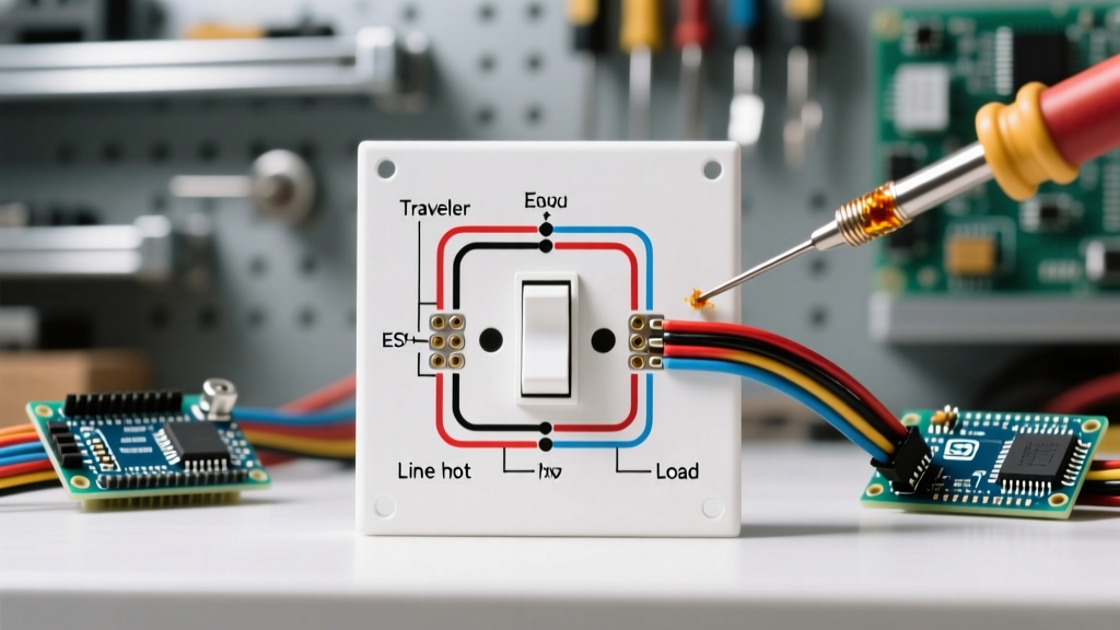

Understanding the Anatomy of a Three-Way Switch
Before diving into any specific wiring diagram for three way switch configurations, it is critical to understand the physical anatomy of the switch itself. Unlike a standard single-pole switch that simply breaks or completes a single hot wire, a three-way switch is essentially a single-pole, double-throw (SPDT) mechanism. It routes the incoming electrical current down one of two possible paths, known as traveler wires.
Every standard three-way switch—such as the widely used Leviton Decora 5603 or the Lutron Claro C-3PS—features four terminal screws:
- The Common Terminal: This is the most crucial connection. It is typically identified by a darker-colored screw (black on Leviton models, dark brass on Lutron models) and is stamped with 'COM' on the switch yoke. It connects to either the incoming line voltage or the outgoing load wire to the light fixture.
- The Traveler Terminals: These are two lighter brass-colored screws. They connect to the traveler wires that run between the two three-way switches. Because the circuit logic is symmetrical, it does not matter which traveler wire goes to which brass screw.
- The Ground Terminal: A green screw located at the bottom of the yoke, which must be connected to the bare copper or green ground wire to ensure safety and NEC compliance.
Standard Wiring Diagram for Three Way Switch: Power at Switch 1
The most common and straightforward wiring diagram for three way switch setups occurs when the main power source (the line) enters the first switch box. This configuration requires standard 2-wire and 3-wire Romex (NM-B) cables.
Step-by-Step Connection Flow
- Power to Switch 1 (Line): The incoming 14/2 or 12/2 cable from the breaker panel enters the first switch box. The bare copper wire connects to the ground pigtail. The white neutral wire is capped off with a wire nut and pushed to the back of the box (it does not connect to a standard mechanical switch). The black hot wire connects directly to the Common (black) screw on Switch 1.
- Switch 1 to Switch 2 (Travelers): A 14/3 or 12/3 cable runs between the two switch boxes. The red and black wires of this 3-wire cable connect to the two brass traveler screws on Switch 1. At Switch 2, these same red and black wires connect to the two brass traveler screws.
- Switch 2 to Light Fixture (Load): The white wire of the 3-wire cable acts as the neutral and passes through Switch 2 to the light fixture. The black wire of a new 14/2 or 12/2 cable connects to the Common (black) screw on Switch 2 and runs to the black (hot) wire of the light fixture. The white wire of this final cable connects to the white (neutral) wire of the light fixture.
NEC 2023/2026 Compliance: The Neutral Wire Requirement
When reviewing any modern wiring diagram for three way switch installations, you must account for NFPA NEC Article 404.2(C). This code mandates that a grounded circuit conductor (the white neutral wire) must be present at every switch location controlling lighting loads.
Why does this matter? The rise of smart home technology means many homeowners eventually upgrade to Wi-Fi or Zigbee-enabled smart switches (like the Lutron Caseta or Leviton Decora Smart). These devices require a neutral wire to power their internal radios and LEDs even when the light is off. Always run a neutral to both switch boxes, even if your current mechanical switch does not require it.
Wire Color Coding & Cable Matrix
| Wire Color | Function in Circuit | Typical Cable Used | NEC Re-Marking Rule |
|---|---|---|---|
| Black | Line (Always Hot) or Load | 14/2 or 12/2 NM-B | None required |
| Red | Traveler 1 | 14/3 or 12/3 NM-B | None required |
| White (Re-marked) | Traveler 2 (in specific setups) | 14/3 or 12/3 NM-B | Must be wrapped in black tape (NEC 200.7(C)) |
| White | Grounded Neutral | All NM-B cables | Must remain white or gray |
| Bare / Green | Equipment Ground | All NM-B cables | None required |
Alternative Configuration: Power Source at the Light Fixture
A more complex wiring diagram for three way switch scenarios occurs when the power source enters the light fixture box first. This is common in older homes or specific architectural layouts where running power to a ceiling junction box is easier than routing it to a wall switch.
In this configuration, you must send power down to the first switch, and then route the travelers to the second switch. According to expert guidelines from Family Handyman, this requires careful re-marking of wires to comply with NEC 200.7(C), which prohibits using a white wire as an ungrounded (hot) conductor unless it is permanently re-identified.
- At the Light Box: The incoming black hot wire and the white neutral wire from the switch cable are spliced together. Crucial Step: You must wrap black electrical tape around both ends of this white wire to indicate it is now carrying line voltage, not neutral.
- At Switch 1: The re-marked white wire (now hot) connects to the Common screw. The black and red wires of the 3-wire cable connect to the traveler screws.
- At Switch 2: The black and red traveler wires connect to the brass screws. The white wire of the 3-wire cable (which is acting as the switched load returning to the light) connects to the Common screw.
Common Failure Modes and Multimeter Troubleshooting
If your three-way circuit is malfunctioning, do not guess. Use a digital multimeter (such as the Fluke 117 True RMS) or a non-contact voltage tester (like the Klein Tools NCVT-2) to diagnose the issue based on common failure modes detailed in Electrical Technology's comprehensive switching guides.
Troubleshooting Matrix
| Symptom | Probable Cause | Diagnostic Action |
|---|---|---|
| Light only turns on from one switch, but not the other. | The line or load wire is incorrectly connected to a traveler screw instead of the Common screw. | Identify the always-hot wire with a voltage tester. Ensure it is on the black/dark brass screw, not a light brass screw. |
| Light toggles on and off, but the switch positions are inverted (e.g., both switches must be 'down' to turn on). | Traveler wires are crossed or wired out of phase with the physical toggle orientation. | Swap the two traveler wires on the brass screws of either Switch 1 or Switch 2. This reverses the logic without breaking the circuit. |
| Breaker trips immediately upon flipping the switch. | Dead short. A hot traveler wire is touching the ground wire or the metal junction box. | Inspect wire nuts and ensure bare copper ground wires are pushed safely away from the brass terminal screws. |
| Smart switch fails to power on or connect to Wi-Fi. | Missing or disconnected neutral wire at the switch box. | Verify the white neutral pigtail is securely connected to the bundle in the back of the box and the switch's neutral lead. |
Frequently Asked Questions
Can I use a 14/3 wire on a 20-amp breaker circuit?
No. If your circuit is protected by a 20-amp breaker, you must use 12 AWG wire exclusively. Using 14/3 wire (which contains 14 AWG conductors) on a 20-amp circuit is a severe fire hazard and a direct violation of NEC Article 240.4(D). Always match the wire gauge to the breaker: 14 AWG for 15A, 12 AWG for 20A.
Does it matter which traveler wire goes to which brass screw?
Electrically, no. The two traveler screws are functionally identical. Swapping the red and black traveler wires will simply invert the physical up/down toggle positions of the switches, but the circuit will still operate correctly.
How do I convert a three-way switch to a smart switch?
Most smart three-way systems (like Lutron Caseta) require you to replace the master switch at the location where the Line voltage enters the box. The secondary switch is either replaced with a proprietary wireless remote (like a Pico remote) or wired as a dumb mechanical switch in a specific bypass configuration, depending on the manufacturer's instructions. Always ensure a neutral wire is present before purchasing a smart switch.