
The Anatomy of a Code-Compliant Camper Trailer Electrical System
Designing a safe and reliable wiring diagram for a camper trailer requires far more than simply connecting a battery to a fuse box. Recreational vehicles operate in one of the most punishing electrical environments possible: a vibrating, temperature-fluctuating, mobile metal and wood enclosure. According to the NFPA 1192 Standard on Recreational Vehicles, electrical failures remain a leading cause of RV fires. To mitigate this, every connection, wire gauge, and overcurrent protection device must strictly adhere to both the National Electrical Code (NEC) Article 551 and RVIA (Recreational Vehicle Industry Association) standards.
In this comprehensive guide, we break down the exact schematic requirements, wire sizing matrices, and component selections needed to build a 2026-compliant camper trailer electrical system that prioritizes life safety and fire prevention.
⚠️ CRITICAL SAFETY WARNING: Never use standard solid-core Romex (NM-B) cable for 120V AC branch circuits inside a camper trailer. Road vibration causes solid copper to work-harden, snap, and arc inside walls. You must use stranded THHN/THWN wire pulled through flexible non-metallic tubing (ENT) or specific RV-rated stranded cables.Decoding the Wiring Diagram for a Camper Trailer: AC vs. DC Separation
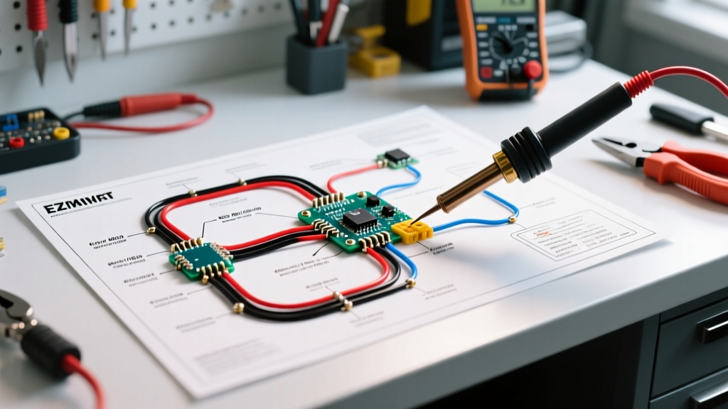
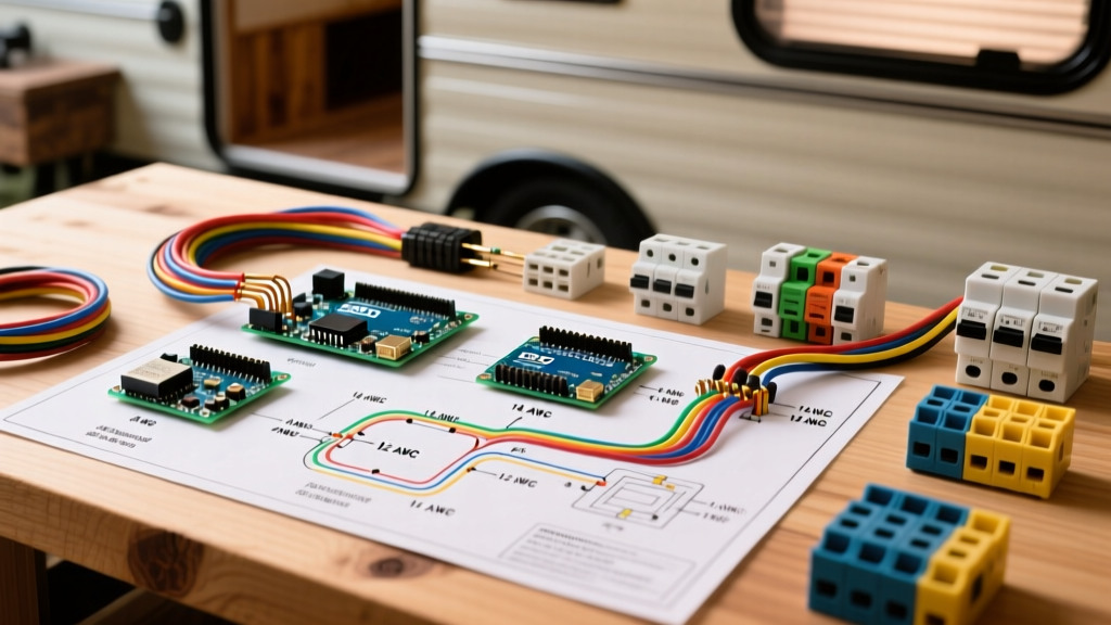
A standard camper trailer wiring diagram is divided into two distinct, isolated systems: the 120V AC shore power system and the 12V DC coach battery system. The most common code violation in DIY camper builds is the improper routing and mixing of these two systems.
NEC Article 551 Separation Mandates
Under NEC Article 551 (Recreational Vehicles and Recreational Vehicle Parks), 120V AC and 12V DC wiring must be physically separated. If they must cross or run parallel, the code dictates specific clearance requirements:
- Parallel Runs: AC and DC wires must be separated by a minimum of 1.5 inches, or divided by a continuous physical barrier (such as a rigid conduit or a dedicated wire loom).
- Crossing Runs: When AC and DC wires must cross, they should do so at 90-degree angles to minimize electromagnetic interference (EMI) and reduce the risk of insulation wear-through.
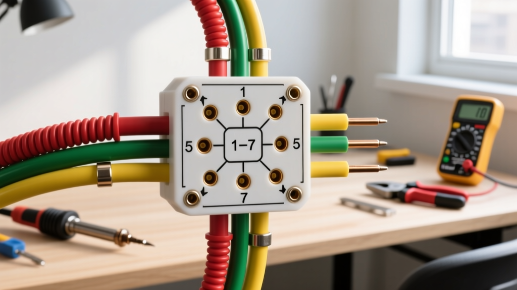
- Junction Boxes: AC and DC connections must never share the same junction box unless the box features a permanently installed, UL-listed physical divider.
Wire Gauge, Ampacity, and Overcurrent Protection Matrix
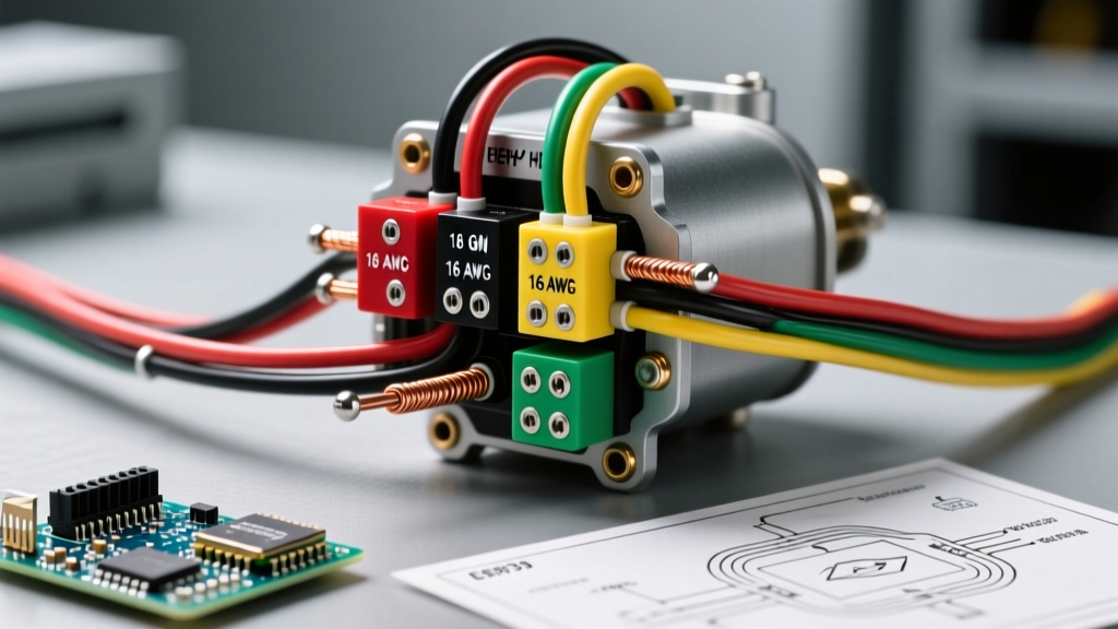
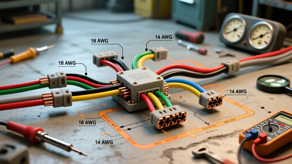
Voltage drop is the silent killer of 12V DC camper systems, while thermal overload is the primary hazard for 120V AC systems. The following matrix outlines the exact wire gauges and breaker sizes required for standard camper trailer circuits in 2026. Note that DC wire runs are calculated based on a 3% maximum voltage drop for critical appliances (like compressor fridges) and a 10% drop for lighting.
| System / Circuit Type | Wire Type | Min. AWG (Up to 25ft) | Overcurrent Protection |
|---|---|---|---|
| 120V AC Main Shore Inlet (30A) | 10 AWG Stranded THHN (3-wire) | 10 AWG | 30A Double-Pole Breaker (Main) |
| 120V AC Rooftop A/C Branch | 12 AWG Stranded THHN | 12 AWG | 20A Single-Pole Breaker |
| 120V AC General Receptacles | 14 AWG Stranded THHN | 14 AWG | 15A or 20A GFCI/AFCI Breaker |
| 12V DC Converter to Battery Bank | 4 AWG SAE J1128 (Stranded) | 4 AWG (or 2 AWG for 60A+) | 50A ANL Fuse (within 7" of battery) |
| 12V DC 12V Compressor Fridge | 10 AWG Marine Tinned | 10 AWG | 15A ATC Blade Fuse |
| 12V DC LED Lighting Runs | 14 AWG or 16 AWG Stranded | 14 AWG | 5A or 10A ATC Blade Fuse |
Essential 2026 Components for Safe RV Wiring
When executing your wiring diagram for a camper trailer, component selection directly impacts code compliance and longevity. Cheap, non-certified Amazon components frequently fail RVIA inspections and pose severe fire risks. Below are the industry-standard, UL-listed components recommended for 2026 builds:
1. Power Conversion and Distribution
- Progressive Dynamics PD4655 (55A Converter/Charger): Priced around $225–$245, this unit features a built-in 120V AC main panel (with spaces for two 30A breakers) and a 12V DC fuse board. Its multi-stage charging algorithm prevents battery overcharging, a common cause of lead-acid thermal runaway.
- Square D Homeline HOM48L125PG: If building a custom AC panel for a 50A shore setup, this 4-space, 125A maximum panel ($48) provides robust, UL-listed bus bar connections that resist vibration loosening.
2. DC Overcurrent Protection
- Blue Sea Systems ST Blade Fuse Block (5025): At approximately $35, this marine-grade fuse block features independent negative bus bars and a tin-plated copper bus, eliminating the voltage drop and corrosion associated with cheap automotive plastic fuse taps.
- Littelfuse MEGA/AMG Fuses: For the main battery disconnect, always use a Class T or ANL fuse within 7 inches of the battery positive terminal, as mandated by ABYC and RVIA standards.
Grounding, Bonding, and the Chassis Connection
One of the most misunderstood aspects of an RV wiring diagram is the grounding scheme. A camper trailer is not a house; it relies on a complex equipotential bonding system to prevent the metal chassis from becoming energized.
"NEC 551.54 explicitly requires the grounding conductor of the 120V AC system to be bonded to the RV chassis. Furthermore, the 12V DC negative system must also be bonded to the chassis. This ensures that if a 120V AC hot wire chafes against the metal frame, the fault current has a low-impedance path back to the source, instantly tripping the breaker and preventing lethal shock hazards."
Executing the Grounding Hierarchy
- Shore Power Inlet Ground: The green grounding wire from the 30A/50A shore cord must connect directly to the grounding bus bar in the main AC distribution panel.
- Panel-to-Chassis Bond: A minimum 8 AWG bare copper bonding wire must connect the AC panel grounding bus to a clean, unpainted metal point on the trailer chassis.
- DC Negative-to-Chassis Bond: The main 12V DC negative bus bar must be bonded to the chassis using a heavy-gauge strap (minimum 4 AWG for systems up to 100A).
- Appliance Grounding: All metal-cased 120V AC appliances (microwaves, A/C units) must have their green grounding wires terminated to the panel's ground bus, not just screwed into the wood cabinetry.
Common Code Violations and Troubleshooting
Even with a perfect wiring diagram for a camper trailer on paper, execution errors in the field lead to catastrophic failures. Avoid these frequent violations:
❌ Violation 1: Using Wire Nuts in High-Vibration ZonesStandard twist-on wire nuts will vibrate loose over thousands of miles of towing. Correction: Use closed-end crimp connectors (heat-shrink lined) or lever-nuts (like WAGO 221 series) secured to a backing plate with a zip-tie anchor.
❌ Violation 2: Undersized Converter WiringRunning 6 AWG wire from a 55A converter to a battery bank located 15 feet away results in severe voltage drop, causing the converter to overheat and the battery to undercharge. Correction: Always calculate the round-trip distance (30 feet total). For a 55A load over 30 feet, upgrade to 2 AWG stranded copper to maintain less than a 2% voltage drop.
Troubleshooting 12V Voltage Drop in the Field
If your 12V Dometic or Furrion compressor refrigerator shuts off intermittently while boondocking, the issue is rarely the fridge itself. It is almost always voltage drop at the wiring terminations. Use a digital multimeter to measure voltage directly at the battery terminals, then measure again at the fridge's terminal block under load. If the drop exceeds 0.5V, inspect your blade fuses for micro-corrosion and upgrade the branch wiring from 12 AWG to 10 AWG.
Conclusion
Building a safe camper trailer electrical system requires strict adherence to the RV Dealers Association guidelines and NEC Article 551. By utilizing stranded copper, enforcing strict AC/DC separation, properly sizing overcurrent protection, and executing a flawless chassis bonding strategy, your wiring diagram for a camper trailer will provide years of safe, reliable power whether hooked to shore power or boondocking off-grid.