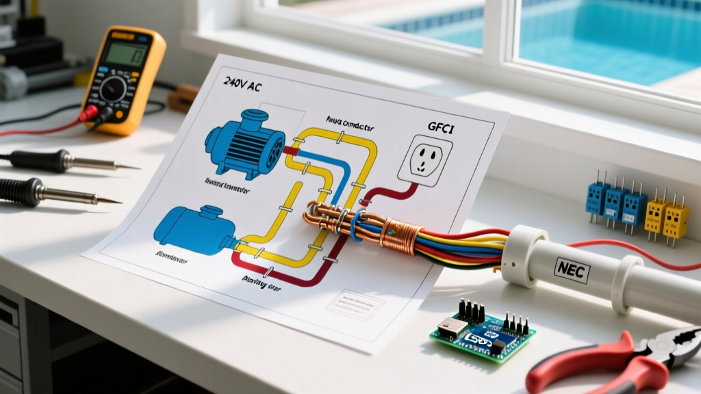

Mastering the Wiring Diagram for Pool Equipment
Wiring a residential swimming pool is not like wiring a standard household appliance. The combination of water, high-amperage 240V motors, and variable frequency drives (VFDs) creates a unique electrical environment governed by strict safety codes. If you are reading a wiring diagram for pool installations, you are likely dealing with a 240V variable speed pump (like the Pentair IntelliFlo3 VSF) and a gas heater (such as the Hayward Universal H-Series).
In 2026, the average cost to professionally wire a new pool equipment pad ranges from $1,800 to $3,500, excluding the equipment itself. However, understanding the schematic allows you to verify contractor work, troubleshoot VFD nuisance tripping, and ensure your equipotential bonding grid passes local Authority Having Jurisdiction (AHJ) inspections.
⚠️ CRITICAL SAFETY WARNING: Pool wiring falls under NEC Article 680. A failure in the equipotential bonding grid can result in fatal voltage gradients in the water. All work must be permitted, inspected, and performed or verified by a licensed electrician.Core Components of a Pool Wiring Schematic
Before pulling THWN-2 wire through Schedule 80 PVC, you must understand the three primary zones depicted in any standard pool wiring diagram:
- The Main Panel to Disconnect: A dedicated 240V circuit with a Class A GFCI breaker.
- The Equipment Pad (Pump & Heater): The integration of the pump motor, heater control board, and fireman's switch.
- The Equipotential Bonding Grid: A continuous #8 AWG solid copper wire linking all metallic components.
1. The GFCI Protected Disconnect
Modern NEC mandates GFCI protection for pool pump motors. For a 240V, 30A circuit, you will typically use a breaker like the Siemens Q230GFCI or Eaton BR230GFCI (retailing around $55–$75 in 2026). The wiring diagram will show two hot legs (Black and Red), a neutral (White), and a ground (Green) running from the main panel to an outdoor weatherproof disconnect box.
2. Variable Speed Pump (VSP) Integration
Variable speed pumps contain internal VFDs that convert AC to DC to drive the motor at varying RPMs. A common edge case in pool wiring diagrams is nuisance GFCI tripping. VFDs generate high-frequency harmonics that older GFCI breakers misinterpret as ground faults. If your diagram includes a VSP, ensure your GFCI breaker is rated for VFD/motor loads, or install a dedicated isolation transformer if specified by the manufacturer.
Step-by-Step Wiring Walkthrough
Follow this sequence to execute the wiring diagram safely and efficiently.
Step 1: Run Conduit and Pull Conductors
Use Schedule 80 PVC conduit for any runs within 5 feet of the pool edge or subject to physical damage. Pull individual THWN-2 conductors. Never use NM-B (Romex) in wet locations or underground conduit. For a standard 2HP pump on a 30A breaker, pull two #10 AWG hot wires (Black, Red), one #10 AWG neutral (White), and one #10 AWG ground (Green).
Step 2: Terminate at the Outdoor Disconnect
Wire the two hot legs to the GFCI breaker's load terminals. Route the neutral to the GFCI neutral bar (not the main ground bar). Connect the equipment grounding conductor (EGC) to the grounding bus. Torque all terminal screws to the manufacturer's specification—typically 15 to 20 in-lbs for standard 30A breakers.
Step 3: Wire the Pool Pump
Open the pump's wiring compartment. Connect Black to L1, Red to L2. Connect the White neutral to the N terminal (required for the pump's internal logic board and digital display). Connect the Green EGC to the pump's grounding screw. Pro Tip: Apply a small amount of Noalox antioxidant compound to the aluminum/copper connections if your pump terminal block is aluminum, though most modern 2026 models use tin-plated copper.
Step 4: Integrate the Gas Heater
Most pool wiring diagrams show the heater wired on a separate 240V circuit, or piggybacking off the pump's load side if the heater's control board draws minimal amperage (under 2A). If wired separately, run a dedicated 20A circuit. Connect the external fireman's switch (usually a dry contact on the pool timer or automation board) to the heater's terminal block to ensure the pump runs for 3 minutes after the heater shuts off, preventing heat exchanger damage.
Wire Sizing & Voltage Drop Matrix
Voltage drop is a critical factor in pool wiring, especially when the equipment pad is far from the main panel. VFDs in modern pumps will throw low-voltage error codes if the voltage drops below 216V on a 240V line.
| Breaker Size | Max Distance (No V-Drop Calc) | Wire Gauge (Copper THWN-2) | Recommended Conduit Size |
|---|---|---|---|
| 20 Amp | Up to 60 feet | #12 AWG | 1/2 inch PVC |
| 30 Amp | Up to 80 feet | #10 AWG | 1/2 inch PVC |
| 40 Amp | Up to 50 feet | #8 AWG | 3/4 inch PVC |
| 50 Amp | Up to 60 feet | #6 AWG | 3/4 inch PVC |
Note: If your run exceeds the distances listed above, you must upsize the wire by one gauge to maintain a voltage drop of less than 3%.
Equipotential Bonding: The #1 Inspection Failure
The most misunderstood part of any pool wiring diagram is the equipotential bonding grid. Grounding and bonding are not the same thing. Grounding provides a path for fault current to trip the breaker. Bonding eliminates voltage gradients between different metallic objects.
According to NFPA 70 (NEC Article 680.26), you must use a solid #8 AWG bare copper wire to bond the following components together in a continuous loop:
- The structural reinforcing steel of the pool shell (rebar).
- All metal coping and deck anchors within 3 feet of the pool edge.
- The pool pump motor housing.
- The gas heater housing and internal water connections.
- Metal ladders, diving stands, and handrails.
- The metal parts of the pool water circulation system (filter tanks, metal PVC fittings).
Bonding Hardware Requirements
Do not use standard steel or zinc-plated clamps for bonding. They will corrode within a single season due to pool chemical exposure. Use only listed bronze or copper grounding clamps (e.g., Burndy or Ilsco bronze lay-in lugs). When connecting to the pool pump, use the dedicated external bonding lug on the motor casing, not the internal equipment grounding screw.
Common Failure Modes & Troubleshooting
The Symptom: The variable speed pump turns on, ramps up to 2400 RPM, and then the GFCI breaker trips immediately.
The Cause: High-frequency leakage current from the VFD's internal capacitors is exceeding the 4-6mA threshold of a standard Class A GFCI breaker.
The Fix: Verify the wiring diagram matches the manufacturer's updated schematic. Ensure the neutral wire is not bonded to the ground at the disconnect. If the wiring is correct, replace the breaker with a model specifically tested for VFD compatibility, or consult the pump manufacturer for a compatible line reactor.
Final Commissioning Checklist
Before filling the pool and energizing the system, verify the following against your wiring diagram:
- Megger Test: Perform an insulation resistance test on all underground conductors before backfilling trenches to ensure no wire jacket damage occurred during pulling.
- Torque Verification: Check all terminal block screws with a calibrated torque screwdriver. Loose connections on 240V pool circuits cause arcing and melted wire insulation.
- Continuity Check: Use a multimeter to verify continuity between the bonding grid and every metallic component within 5 feet of the pool. Resistance should read less than 1 ohm.
- GFCI Test: Press the 'Test' button on the GFCI breaker to ensure mechanical functionality before allowing anyone in the water.
For comprehensive safety guidelines and electrocution prevention data, always refer to the official resources provided by the U.S. Consumer Product Safety Commission's Pool Safely campaign. Proper execution of your pool wiring diagram ensures a safe, efficient, and code-compliant backyard oasis for years to come.