
Introduction to EV Thermal Management and 12V Fan Circuits
When engineering an electric vehicle (EV) conversion or upgrading an OEM thermal management system (TMS), the cooling architecture is just as critical as the high-voltage traction battery. Unlike internal combustion engines, EVs require precise cooling for the inverter, DC-DC converter, and onboard charger. Planning your electric car fan wiring diagram requires moving beyond simple on/off relays and embracing variable-speed Pulse Width Modulation (PWM) control. This not only optimizes aerodynamic efficiency by reducing parasitic drag but also prevents severe voltage sag on the vehicle's 12V auxiliary system.
According to the U.S. Department of Energy's Electric Vehicle Infrastructure guidelines, thermal management systems account for a significant portion of auxiliary power consumption. A poorly planned 12V fan circuit can easily overwhelm the vehicle's DC-DC converter, triggering low-voltage fault codes and shutting down critical CAN bus communications. This installation planning guide details the exact components, wire gauges, and circuit topologies required for a robust EV cooling fan setup.
Core Components of an Electric Car Fan Circuit
Before routing a single wire, you must select components that can handle the harsh under-hood environment and the specific electrical characteristics of an EV. Standard brushed radiator fans draw massive inrush currents that can trip sensitive EV battery management system (BMS) protections. We recommend the following architecture:
- Brushless Fan Motor: Brushless motors, such as the SPAL VA13-BP70/LL-61A (approx. $280-$320), eliminate carbon dust, offer IP68 waterproofing, and feature a soft-start ramp-up that limits inrush current to under 15A, compared to the 60A+ spikes seen in cheap brushed alternatives.
- PWM Fan Controller: The Davies Craig LCD Fan Controller (approx. $145) allows you to set target temperatures and outputs a 20kHz PWM signal. This high frequency is crucial in EVs to prevent electromagnetic interference (EMI) with high-voltage isolation monitors.
- Heavy-Duty Relay: A Bosch/Hella 0 332 209 150 (40A continuous, 5-pin mini-relay) acts as the primary high-current switch, isolating the PWM controller's internal logic from the main power feed.
- Marine-Grade Wiring: Ancor tinned copper wire is mandatory. Standard copper oxidizes rapidly in the high-humidity undercarriage environments common in EV conversions.
Pro-Tip: EV DC-DC Converter Load Budgeting
Most OEM and aftermarket EV DC-DC converters (which step down the 400V/800V traction battery to 12V) are rated between 1.5kW and 2.5kW (roughly 120A to 200A at 13.8V). If your electric cooling fan draws 35A, and your electric power steering (EPS) draws 50A, you are already consuming over half of your 12V budget. Always calculate your peak 12V load and ensure your fan controller limits maximum duty cycle to 85% to leave a safety margin for voltage spikes.
Step-by-Step Electric Car Fan Wiring Diagram Breakdown
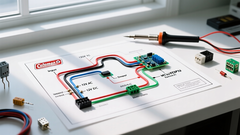
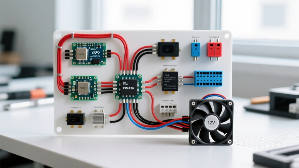
The following topology outlines a professional-grade, PWM-controlled single fan installation. This circuit ensures the fan only receives power when the EV is in 'Ready' mode, preventing the fan from draining the 12V AGM/LiFePO4 auxiliary battery when the car is parked.
Stage 1: High-Current Power and Ground Routing
- Main Power Feed: Run an 8 AWG tinned copper wire from the positive terminal of the 12V auxiliary battery (or the main DC-DC converter output stud). Install a 50A Marine-grade ANL or Class-T fuse within 6 inches of the power source.
- Relay Integration (Power In): Route the fused 8 AWG wire to Pin 30 of the Bosch 40A relay.
- Relay to PWM Controller: Run a 10 AWG wire from Relay Pin 87 (Normally Open) to the 'Power In' terminal on the Davies Craig PWM controller.
- PWM to Fan: Run a 10 AWG wire from the PWM controller's 'Motor +' output to the positive terminal of the brushless fan.
- Grounding Strategy: Ground the fan's negative terminal directly to the chassis using a dedicated, sanded-to-bare-metal grounding stud. Do not daisy-chain grounds with other accessories; this creates ground loops that introduce noise into the EV's low-voltage CAN bus lines.
Stage 2: Logic, Trigger, and Sensor Wiring
- Ignition Trigger: Tap into a 12V 'Ignition ON' source (e.g., the EV's main contactor pre-charge circuit or accessory fuse box). Run an 18 AWG wire through a 5A inline fuse to Relay Pin 86.
- Relay Ground: Ground Relay Pin 85 to the chassis.
- Thermal Probe Placement: The PWM controller requires a temperature sensor. In an EV conversion, strap the thermal probe directly to the inverter's water-cooling plate or the liquid-to-air heat exchanger's outlet hose using high-temp Kapton tape and zip ties. Coat the sensor in thermal paste for rapid response times.
- Signal Shielding: Because EVs generate massive EMI from the inverter's switching frequencies (often 10kHz-20kHz), route all low-voltage sensor and trigger wires inside a braided copper shielding sleeve, grounding the shield at one end only to prevent ground loops.
Wire Gauge and Fuse Sizing Matrix
Proper wire sizing is non-negotiable. The National Fire Protection Association (NFPA) emphasizes that undersized wiring in EV auxiliary systems is a leading cause of thermal runaway in non-battery components. Use the matrix below to size your wires based on the total continuous amperage of your fan setup. Note that wire lengths over 10 feet require stepping up one AWG size to compensate for voltage drop.
| Fan Configuration | Peak Amp Draw | Minimum Wire Gauge (AWG) | Main Fuse Rating | Relay Requirement |
|---|---|---|---|---|
| Single 11" Brushless Fan | 20A - 25A | 10 AWG | 35A (Class-T / ANL) | Single 40A Bosch Relay |
| Single 16" Brushless Fan | 30A - 38A | 8 AWG | 50A (Class-T / ANL) | Single 60A Heavy-Duty Relay |
| Dual 11" Brushless Fans | 40A - 50A | 6 AWG | 70A (Mega / ANL) | Dual 40A Relays (Parallel) |
| Dual 16" Brushless Fans | 60A - 75A | 4 AWG | 100A (Mega / ANL) | Solenoid Contactor (100A+) |
Common Failure Modes and Advanced Troubleshooting
Even with a flawless schematic, EV-specific electrical quirks can cause fan circuit failures. Here are the most common edge cases encountered during dyno and road testing:
1. CAN Bus EMI and Inverter Faults
Symptom: The cooling fan ramps up, but immediately triggers a 'Motor Controller Fault' or 'Loss of Communication' code on the EV dashboard.
Cause: The PWM controller is emitting electrical noise that couples into the unshielded CAN High/CAN Low twisted pair.
Solution: Ensure the PWM switching frequency is set above 18kHz. Install a ferrite choke (e.g., Fair-Rite 2643625302) on the power feed wire within 2 inches of the PWM controller. Verify that the CAN bus wiring is physically routed at least 12 inches away from the fan power cables.
2. DC-DC Converter Thermal Shutdown
Symptom: The 12V system voltage drops below 12.0V during heavy traffic or fast charging, and the fan stutters or shuts off entirely.
Cause: The fan's continuous draw, combined with the AC compressor and power steering, exceeds the DC-DC converter's thermal or current limit, forcing it into protection mode.
Solution: Reprogram the fan controller's maximum duty cycle to 80%. Alternatively, install a secondary 12V LiFePO4 buffer battery (e.g., a 20Ah Battle Born or Dakota Lithium) in parallel with the main AGM battery to absorb transient current spikes without overloading the DC-DC converter.
3. Thermal Hysteresis and Short-Cycling
Symptom: The fan rapidly clicks on and off every 2-3 seconds when the EV is idling at a charger.
Cause: The thermal probe is placed too close to the fan's airflow, or the hysteresis gap on the controller is set too narrow (e.g., ON at 40°C, OFF at 39°C).
Solution: Relocate the probe to the liquid coolant outlet where heat soak is most accurate. Adjust the controller's hysteresis settings to a 4°C delta (e.g., ON at 42°C, OFF at 38°C) to allow the thermal mass of the liquid to stabilize.
Final Verification and Safety Standards
Before applying high voltage to the traction system, perform a low-voltage bench test. Use a variable DC power supply set to 13.8V to simulate the DC-DC converter. Apply heat to the thermal probe using a heat gun while monitoring the current draw with a digital clamp meter. Verify that the fan ramps up smoothly from 20% to 100% duty cycle without any audible clicking from the relay or voltage drops below 12.5V at the fan terminals.
For further reading on automotive electrical standards and thermal management component selection, refer to the Mouser Automotive Applications Engineering portal, which provides extensive datasheets on brushless motor drivers and high-current automotive relays. Proper execution of your electric car fan wiring diagram ensures your EV runs cool, efficient, and safe for hundreds of thousands of miles.