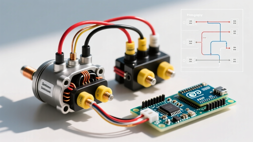

Understanding the Starter Motor Solenoid
The starter motor solenoid is the critical electromagnetic bridge between your vehicle's low-current ignition switch and the high-current starter motor. When you turn the key, the solenoid's internal pull-in and hold-in windings energize, forcing a heavy copper plunger to bridge the main contacts. This action simultaneously engages the starter drive gear with the flywheel and routes hundreds of amps from the battery to the starter motor. Wiring this component incorrectly can result in catastrophic electrical fires, melted harnesses, or a starter that refuses to disengage (run-on). This comprehensive wiring diagram for starter motor solenoid configurations provides a meticulous, step-by-step walkthrough for both 3-post and 4-post setups, ensuring safe, reliable cranking power.
Solenoid Configurations: 3-Post vs. 4-Post
Before cutting wire or stripping lugs, you must identify your solenoid type. The physical terminal layout dictates the wiring diagram you will follow. The 3-post design is ubiquitous in GM/Chevy applications and modern EFI vehicles, while the 4-post design is the hallmark of classic Ford vehicles and older points-ignition systems.
| Feature | 3-Post Solenoid (GM / Modern Style) | 4-Post Solenoid (Ford / Classic Style) |
|---|---|---|
| Main Terminals | B (Battery), M (Motor) | B (Battery), M (Motor) |
| Control Terminal | S (Start / Ignition Switch) | S (Start / Ignition Switch) |
| Bypass Terminal | None (Handled by ignition switch) | I (Ignition Coil Bypass) |
| Primary Application | Most GM vehicles, modern EFI engines | Classic Ford, older points-style ignitions |
| Mounting Style | Typically mounted directly on starter | Often remote-mounted on fender well |
Required Tools and Material Specifications
Automotive starting systems demand high-amperage components. Using undersized wire or improper crimping methods will cause severe voltage drop, leading to slow cranking and premature solenoid failure. According to the SAE J1128 standard for low-tension primary and battery cables, wire gauge must be matched to the engine's displacement and cranking amperage.
- Main Power Cables: 1/0 AWG (or 2 AWG minimum) stranded copper welding cable for engines up to 5.0L. Use 2/0 AWG for high-compression or diesel applications.
- Control Circuit Wire: 10 AWG or 12 AWG stranded primary wire (GXL or TXL cross-linked insulation) for the S and I terminals.
- Terminals: Heavy-duty copper lugs with 3/8" or 5/16" stud holes (matching your solenoid). Avoid cheap aluminum or copper-clad aluminum (CCA) lugs.
- Tools: Ratcheting lug crimper, wire stripper, digital multimeter (DMM), torque wrench (inch-pound scale), and dielectric grease.
Step-by-Step Wiring Walkthrough
Follow this sequence strictly. Always begin with the battery disconnected to prevent accidental short circuits, which can instantly weld your tools to the chassis and cause severe burns.
Step 1: Chassis Grounding and Safety Prep
Disconnect the negative battery terminal first. Clean the engine block grounding point and the chassis grounding point using a wire wheel. The starter motor grounds through its mounting flange to the engine block, and the engine block must have a dedicated, clean ground strap (minimum 1/0 AWG) connecting it to the chassis and battery negative. Poor grounding forces return current through unintended paths, destroying sensors and wiring harnesses.
Step 2: Wiring the B-Terminal (Battery Input)
The B-terminal (sometimes labeled BAT) is the constant 12V input directly from the battery's positive post. Route your 1/0 AWG cable from the battery to the solenoid. Strip exactly 5/8" of insulation, insert it into the copper lug, and crimp using a ratcheting tool. Slide heat-shrink tubing over the connection and apply heat. Attach the lug to the B-terminal stud. Torque specification: Tighten the nut to 90-110 in-lbs (10-12 Nm). Over-torquing will crack the bakelite or plastic insulator cap, causing a dead short to the solenoid casing.
Step 3: Wiring the M-Terminal (Motor Output)
The M-terminal (sometimes labeled MOT) feeds power to the starter motor itself. If your solenoid is remote-mounted (fender well), run a second 1/0 AWG cable from the M-terminal to the starter motor's main lug. If the solenoid is starter-mounted (GM style), the M-terminal is typically connected to the motor via a short, heavy copper braided strap or a rigid copper busbar pre-installed by the manufacturer. Ensure the connection is tight and coated with dielectric grease to prevent corrosion.
Step 4: Wiring the S-Terminal (Start Signal)
The S-terminal activates the solenoid's internal electromagnet. Run a 10 AWG wire from the ignition switch's "Start" position to the S-terminal. On modern vehicles, this wire may route through a neutral safety switch, clutch interlock switch, or an anti-theft relay before reaching the solenoid. Use a female spade connector (usually 1/4" blade) for the S-terminal. Crimp and heat-shrink the connection. When the key is turned to "Start," this wire delivers 12V to pull the plunger inward.
Step 5: Wiring the I-Terminal (Ignition Bypass - 4-Post Only)
If you are working with a 4-post Ford-style solenoid, you will see an "I" terminal (Ignition). During cranking, the starter draws massive current (200-400 amps), which can cause system voltage to drop below 9 volts. In older points-style or early electronic ignition systems, this voltage drop starves the ignition coil, resulting in a weak spark and a no-start condition. The I-terminal acts as a bypass: when the solenoid engages, it sends full battery voltage directly to the positive side of the ignition coil. Connect a 12 AWG wire from the I-terminal to the coil's positive terminal. Note: Modern EFI and HEI (High Energy Ignition) systems do not require this bypass and should use a 3-post solenoid or leave the I-terminal disconnected.
Expert Pro-Tip: Never use the I-terminal to power aftermarket accessories or secondary relays. It is only energized during the exact moment of cranking and drops to 0V the moment you release the key to the "Run" position.
Testing and Voltage Drop Diagnostics
Once the wiring diagram for starter motor solenoid connections is fully executed, you must validate the circuit. The AutoShop 101 Starting Systems guide emphasizes that voltage drop testing is the only accurate method to diagnose high-resistance faults in heavy-gauge circuits. Set your digital multimeter to DC Volts.
| Test Point | Red Probe (+) | Black Probe (-) | Acceptable Reading (Cranking) | Indication if High |
|---|---|---|---|---|
| Solenoid Main Drop | B-Terminal Stud | M-Terminal Stud | Less than 0.15V | Pitted internal contacts or loose lug |
| Positive Cable Drop | Battery Post | B-Terminal Stud | Less than 0.20V | Corroded battery clamp or undersized wire |
| Ground Circuit Drop | Battery Negative | Starter Motor Case | Less than 0.20V | Faulty engine-to-chassis ground strap |
| Control Circuit Drop | Ignition Switch "Start" | S-Terminal | Less than 0.50V | Failing neutral safety switch or thin wire |
Common Failure Modes and Edge Cases
Even with a perfect wiring diagram for starter motor solenoid execution, environmental and mechanical factors can introduce edge cases. Understanding these failure modes is crucial for long-term reliability.
1. Solenoid "Run-On" (Welded Contacts)
If the battery is severely depleted or the engine is mechanically seized, the starter may draw excessive amperage while the voltage plummets. This low-voltage, high-amperage state can cause the internal copper plunger to arc violently against the B and M contacts. The arc generates enough heat to literally melt and weld the contacts together. When you release the key, the S-terminal loses power, but the B and M terminals remain physically fused, causing the starter to spin continuously until the battery dies or the cable melts. Fix: Replace the solenoid and load-test the battery.
2. The "Click-Click-Click" Rapid Cycle
If you turn the key and hear a rapid machine-gun clicking noise, the solenoid is engaging but immediately dropping out. This occurs when the control circuit (S-terminal) has enough voltage to pull the plunger in, but the moment the heavy B-to-M contacts close, the starter draws massive current, pulling the entire system voltage down. The voltage at the S-terminal drops below the solenoid's "hold-in" threshold, releasing the plunger. Voltage rebounds, and the cycle repeats. This is almost always caused by a dead battery, severely corroded battery terminals, or an undersized main cable.
3. Parasitic Draw from Miswired Control Circuits
A common DIY mistake is wiring the S-terminal to a switched 12V source that remains hot in the "Run" position rather than the "Start" position. This will keep the solenoid's hold-in winding energized continuously while driving. The hold-in winding is not designed for continuous duty; it will overheat, melt the internal coil insulation, and eventually cause a parasitic draw that drains the battery overnight or starts an electrical fire. Always verify the S-terminal wire only has 12V during the physical "Start" key position using a multimeter.
For further diagnostic procedures and advanced starting system troubleshooting, refer to the AA1Car starter diagnostic procedures. Proper execution of this wiring diagram ensures your vehicle will start reliably in any condition, protecting both your starter motor and your vehicle's electrical ecosystem.