
The Motor-Control Philosophy for Resistive Heating
In electrical training, motor wiring tutorials teach us how to safely switch high-amperage inductive loads using low-voltage signals via heavy-duty contactors. While a 220 volt baseboard heater is a purely resistive load rather than an inductive motor, any heating array exceeding 16 amps demands the exact same robust contactor wiring architecture used for 220V well pumps or HVAC compressors. Standard line-voltage thermostats are typically rated for a maximum of 16 to 22 amps. When you push beyond this threshold, the internal bimetallic switches or solid-state relays inside the thermostat will overheat, arc, and eventually weld themselves shut—a catastrophic failure mode that leaves your heater running indefinitely.
By applying motor-control logic to resistive heating, we isolate the high-current 220V path from the delicate control circuit. This guide provides the definitive wiring diagram for 220 volt baseboard heater installations, bridging the gap between simple direct-wire setups and advanced, multi-zone contactor arrays that integrate seamlessly with modern smart thermostats like the Ecobee SmartThermostat or Nest Learning Thermostat.
NEC Article 424 and the 125% Continuous Load Rule
Before pulling any 12/2 or 10/2 NM-B (Romex) cable, you must calculate your circuit capacity according to the National Electrical Code (NEC). Fixed electric space-heating equipment falls under NEC Article 424. Because baseboard heaters are designed to run for three hours or more during peak winter months, the NEC classifies them as continuous loads.
NEC Article 424.3(B) Branch-Circuit Sizing: Branch circuits supplying two or more outlets for fixed electric space-heating equipment shall be rated at not less than 125 percent of the total heating load.
This means a standard 20-amp double-pole breaker cannot safely supply 4800 watts (20A x 240V). You must derate the breaker by 80% (or multiply the load by 125%). Therefore, the maximum continuous load on a 20-amp breaker is 16 amps, which equals 3840 watts at 240 volts. If your baseboard heater array exceeds 3840W, you must step up to a 30-amp breaker and 10 AWG wire, and you must use a heavy-duty contactor to manage the switching.
Sizing Matrix: Breakers, Wires, and Wattage
Use the following reference table to determine the correct wire gauge, breaker size, and switching mechanism for your specific 220V baseboard heater setup. This matrix assumes a standard 240V split-phase residential supply.
| Heater Wattage | Amperage (240V) | Min Wire Gauge | Breaker Size | Max Continuous Load | Required Switching |
|---|---|---|---|---|---|
| 1000W | 4.1A | 14 AWG (12 rec.) | 15A | 12A (2880W) | Line-Voltage Thermostat |
| 1500W | 6.2A | 14 AWG (12 rec.) | 15A | 12A (2880W) | Line-Voltage Thermostat |
| 2000W | 8.3A | 12 AWG | 20A | 16A (3840W) | Line-Voltage Thermostat |
| 2500W | 10.4A | 12 AWG | 20A | 16A (3840W) | Line-Voltage Thermostat |
| 4000W | 16.6A | 10 AWG | 30A | 24A (5760W) | Contactor + LV Thermostat |
| 6000W | 25.0A | 10 AWG | 40A | 32A (7680W) | Contactor + LV Thermostat |
Direct-Wire Diagram: Line-Voltage Thermostats (Under 16A)
For single-room installations utilizing a unit like the Cadet F2524W (2500W, 240V), a direct-wire configuration is standard. In this setup, the 220V circuit from the breaker panel feeds directly into a double-pole line-voltage thermostat (such as the Honeywell CT410B), which then routes the switched 220V to the heater.
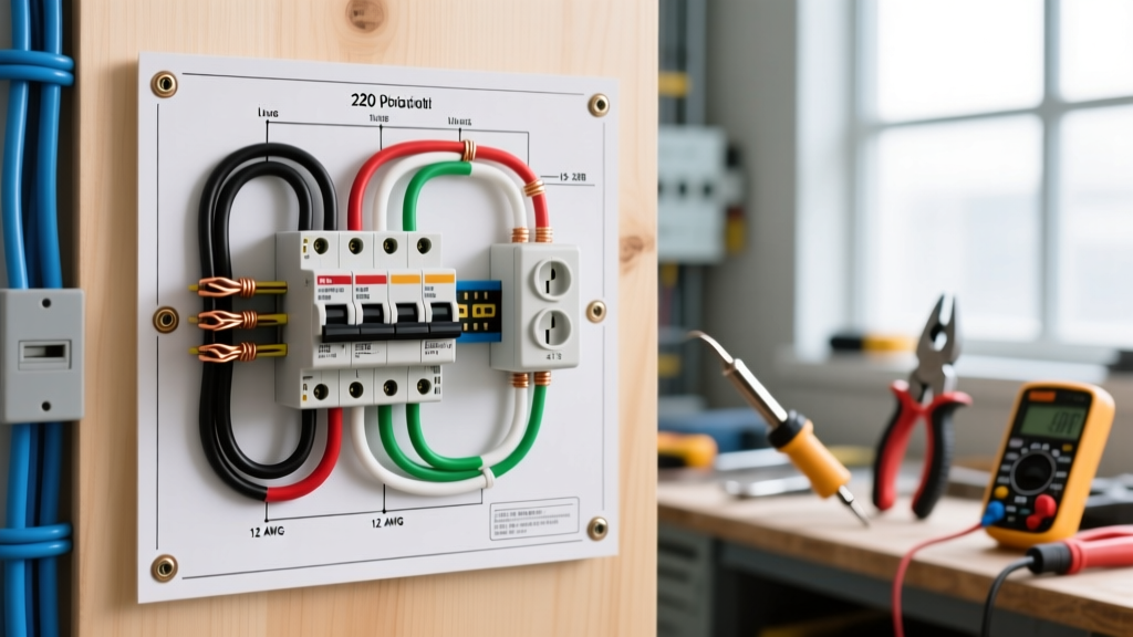
- Panel to Thermostat: 12/2 NM-B with ground. The black and white wires (re-identified with black tape) connect to the L1 and L2 line terminals on the thermostat.
- Thermostat to Heater: The T1 and T2 load terminals on the thermostat connect to the two heating element leads inside the baseboard junction box.
- Grounding: The bare copper ground wire must be bonded to the green grounding screw in the thermostat box and the metal chassis of the baseboard heater.
Expert Tip: Always use a torque screwdriver set to the manufacturer's specification (typically 12 to 14 in-lbs for 12 AWG wire) to prevent terminal loosening due to thermal expansion and contraction cycles.
Advanced Contactor Wiring Diagram: High-Capacity Arrays
When wiring a whole-floor array or a single massive 4000W+ baseboard heater, we borrow from motor-starting circuits. We use a Definite Purpose Contactor or a heavy-duty relay like the Honeywell R8222U1000 (a DPST 30A relay). This allows us to use a low-voltage (24V) smart thermostat to control the 220V load safely.
Step-by-Step Contactor Installation
- Mount the Contactor: Install the Honeywell R8222U1000 in a standard 4x4 steel junction box near the heater array. Ensure adequate clearance for heat dissipation.
- Wire the 24V Control Circuit: Mount a 24VAC transformer (e.g., Honeywell AT72D1683) near the panel. Run 18/2 thermostat wire from the transformer to your smart thermostat's 'R' and 'W' terminals, and then from the thermostat to the contactor's coil terminals (A1 and A2).
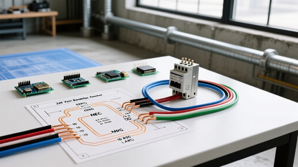
- Wire the 220V Line Side: Run 10/2 NM-B from a 30A double-pole breaker to the L1 and L2 line terminals on the contactor. Do not switch the neutral or ground.
- Wire the 220V Load Side: Run 10/2 NM-B from the T1 and T2 load terminals on the contactor to the baseboard heater array junction box.
- Bond Grounds: All bare copper grounds must be continuous and bonded to every metal junction box and the heater chassis using green grounding screws or wire nuts.
Real-World Failure Modes and Edge Cases
Even with a perfect wiring diagram for 220 volt baseboard heater systems, field conditions introduce variables that can cause system failure. Understanding these edge cases separates DIYers from master electricians.
- Contactor Chatter: If the contactor rapidly clicks on and off, the coil is not receiving sufficient voltage. This is often caused by voltage drop over long runs of 18-gauge thermostat wire. Fix: Upgrade the control wire to 16 AWG or move the 24V transformer closer to the thermostat.
- Welded Thermostat Contacts: If you bypass the contactor and wire a 4000W heater directly to a 22A line-voltage thermostat, the initial inrush current and continuous thermal load will pit and weld the internal contacts. The heater will refuse to turn off, posing a severe fire hazard.
- Voltage Drop on Long Runs: If your 10/2 NM-B cable run from the panel to a 6000W baseboard heater exceeds 80 feet, you will experience a voltage drop greater than 3%. This reduces heating efficiency and causes the amperage to spike, potentially tripping the breaker. Fix: Upsize the wire to 8 AWG for runs over 80 feet.
- Thermal Cutoff Tripping: Baseboard heaters feature an internal high-limit thermal cutoff switch. If furniture or heavy drapes are placed within 6 inches of the heater's convection fins, the trapped heat will trip this switch. This is a manual-reset or auto-reset safety feature, not an electrical wiring fault.
Authoritative References
Safe electrical installations require adherence to national and occupational standards. The wiring diagrams and load calculations presented in this guide are based on current industry standards and safety protocols. For further reading and code verification, consult the following authoritative resources:
- National Fire Protection Association (NFPA): Review the complete National Electrical Code (NEC) guidelines, specifically Article 424 regarding fixed electric space-heating equipment and Article 210 for branch circuit requirements.
- U.S. Department of Energy (DOE): Explore the Energy Saver Home Heating Systems portal for data on resistive heating efficiency, thermostat placement, and energy consumption metrics.
- Occupational Safety and Health Administration (OSHA): Consult the OSHA Electrical Safety standards for lockout/tagout (LOTO) procedures and safe work practices when terminating 220V circuits.
By treating high-wattage resistive heaters with the same respect and architectural rigor as heavy-duty motor loads, you ensure a heating system that is not only highly efficient but fundamentally safe for decades of continuous operation.