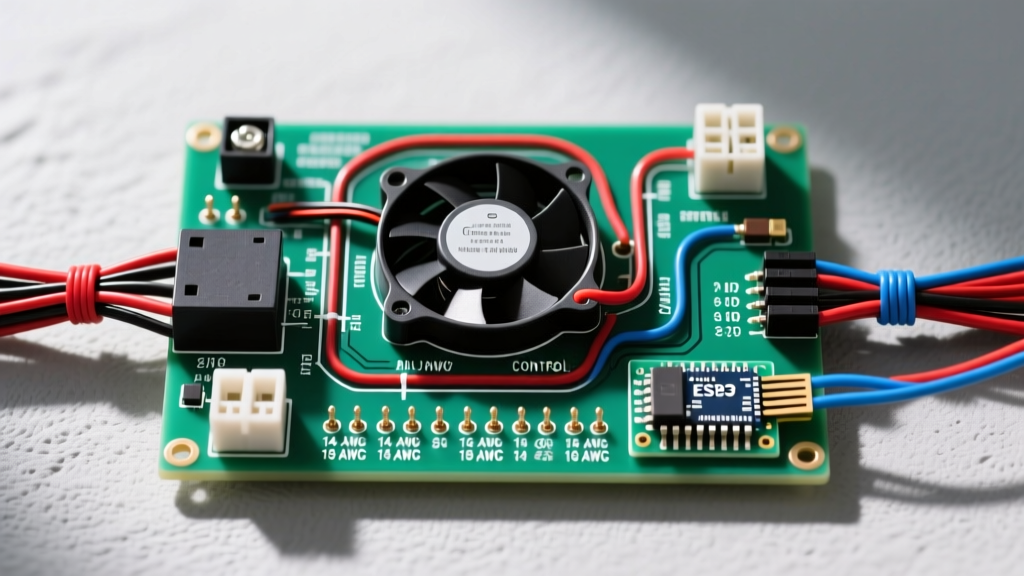

Upgrading to Electric: The Importance of a Flawless Wiring Plan
Transitioning from a mechanical clutch fan to an electric cooling setup is one of the most effective bolt-on modifications for freeing up parasitic drivetrain loss—often recovering 10 to 15 horsepower at the rear wheels. However, the success of this upgrade hinges entirely on executing a proper car electric fan wiring diagram. Electric cooling fans draw massive inrush currents upon startup and sustain high continuous amperage during operation. A poorly planned harness will result in melted bulkhead connectors, severe voltage drop, or a dead battery. This installation planning guide provides the exact engineering parameters, component selections, and routing strategies required for a reliable, high-amperage automotive cooling circuit in 2026.
Sizing Your Electric Fan and Relay System
Before cutting a single zip tie, you must match your wire gauge and relay capacity to the specific amperage draw of your chosen fan assembly. Undersizing the primary power wire is the leading cause of electrical fires in aftermarket cooling systems. While the NFPA 70 National Electrical Code provides baseline ampacity tables for copper wire, automotive under-hood environments require derating due to extreme ambient heat. Always use wire rated to SAE J1128 standards for primary automotive cable, which features cross-linked polyethylene (XLPE) insulation rated for 125°C.
| Fan Configuration | Avg. Continuous Draw | Inrush Current | Min. Primary Wire Gauge | Recommended Relay & Fuse |
|---|---|---|---|---|
| Single 12" Standard | 15A - 18A | ~35A | 12 AWG | 30A Relay / 25A MAXI Fuse |
| Single 16" High-CFM | 22A - 26A | ~55A | 10 AWG | 40A Relay / 30A MAXI Fuse |
| Dual 12" Pullers | 30A - 36A | ~70A | 8 AWG | 50A Relay / 40A MAXI Fuse |
| 15" Brushless PWM | 10A - 18A (Variable) | ~20A (Soft Start) | 10 AWG | 30A Relay / 25A MAXI Fuse |
The Core Car Electric Fan Wiring Diagram Explained
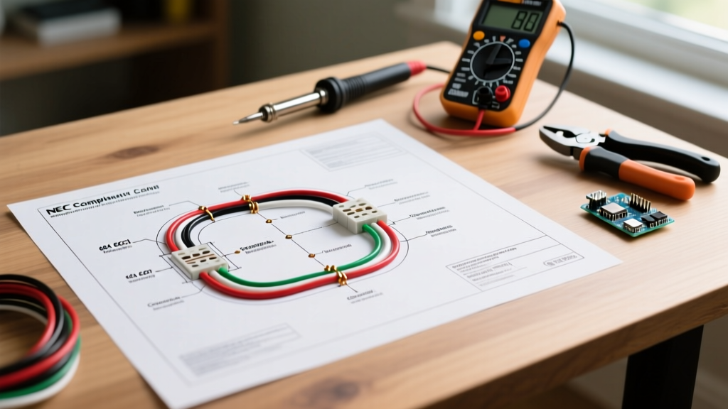
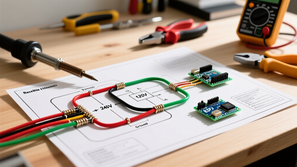
The industry standard for high-amperage automotive switching is the Bosch-style ISO mini relay (commonly part number JD1914). When planning your car electric fan wiring diagram, you will utilize a standard 4-pin configuration. Understanding the internal coil and contact mechanism is critical for troubleshooting.
Standard 4-Pin Relay Pinout Breakdown
- Pin 30 (Common Input): This is your high-amperage 12V constant power feed directly from the battery positive terminal. It must pass through an inline MAXI fuse located within 6 inches of the battery.
- Pin 87 (Normally Open Output): This terminal routes the switched 12V power to the positive terminal of the electric fan motor. When the relay engages, Pin 30 connects to Pin 87.
- Pin 85 (Coil Ground): This provides the ground path for the relay's internal electromagnetic coil. It should be grounded to a clean, unpainted chassis point or directly to the battery negative.
- Pin 86 (Coil Trigger): This is your low-amperage 12V switched signal. It receives power from your thermostat switch, ECU fan control module, or manual dashboard toggle to activate the coil.
Component Selection & 2026 Budgeting
Sourcing high-quality electrical components prevents premature failure. Cheap, unbranded relays often use substandard copper alloys in the contact points, leading to internal arcing and welded contacts (where the fan refuses to turn off). Plan your budget around premium OEM-style components.
- Bosch JD1914 40A Relay (Part #0332014150): ~$14.00. The gold standard for automotive high-current switching. Features a built-in resistor to suppress coil voltage spikes.
- Littelfuse MAXI Fuse Holder & 30A Fuse: ~$12.00. MAXI fuses handle high inrush currents better than standard ATO blade fuses, which can suffer from fatigue cracking under repeated thermal cycling. Reference the Littelfuse automotive fuse catalog for exact time-delay curves.
- Thermostatic Switch Kit (e.g., Derale Part #16749): ~$45.00. Includes an adjustable billet probe that threads directly into your radiator petcock or upper hose adapter.
- SAE J1128 10 AWG Primary Wire (25ft spool): ~$35.00. Ensure it is stranded copper, not copper-clad aluminum (CCA), which has higher resistance and is prone to breaking under engine bay vibration.
- Weatherpack Connectors & Heat Shrink: ~$20.00. Essential for sealing the connections at the fan motor and relay.
Total Estimated Electrical Component Cost: $126.00 (excluding the fan assembly itself).
Step-by-Step Installation & Routing Strategy
1. Main Power and Fusing
Route the 10 AWG primary power wire from the battery positive terminal, through the engine bay, to the relay mounting location. Keep this wire away from exhaust headers and sharp sheet metal edges. Install the MAXI fuse holder immediately at the battery. If the wire chafes against the chassis downstream of the fuse, the battery will dump hundreds of cold cranking amps directly into the short, instantly starting a fire.
2. Trigger Circuit Integration
You have three primary options for triggering Pin 86 on your relay:
- Autonomous Thermostat Probe: The simplest method. The probe senses coolant temperature and sends 12V to Pin 86 when the threshold (e.g., 185°F) is reached. Wire the probe's power feed to an ignition-switched 12V source so the fan cannot run after the engine is turned off.
- ECU PWM Integration: Modern engines (and many aftermarket EFI systems like Holley Terminator X) use a Pulse Width Modulated (PWM) signal to control fan speed. Warning: You cannot wire a raw ECU PWM signal directly to a standard relay coil. You must use a dedicated PWM relay driver module to translate the ECU's low-side ground signal into a 12V relay trigger.
- Manual Override: Wire a heavy-duty toggle switch on the dashboard. Always use a secondary 5A inline fuse for this cockpit wiring run.
Common Failure Modes & Troubleshooting
Expert Warning: The Radiator Support Grounding Mistake
Never ground the electric fan motor directly to the radiator support or core support. These panels are typically spot-welded to the chassis and coated in thick paint or powder coat. The high amperage draw of the fan will cause severe voltage drop across the paint, leading to slow fan speeds, overheating, and melted ground wires. Always run a dedicated 10 AWG ground wire from the fan motor directly to the engine block or the battery negative terminal.
Diagnosing Voltage Drop
If your fan sounds sluggish or cycles on and off rapidly, perform a voltage drop test. Set your digital multimeter to DC Volts. Place the red probe on the battery positive terminal and the black probe on the fan's positive input wire while the fan is running. A healthy circuit will show a voltage drop of less than 0.2V. If you read 0.5V or higher, you have excessive resistance in the wire, a corroded MAXI fuse blade, or a failing relay contact.
Advanced Planning: Brushless Motor Upgrades
As of 2026, brushless electric fans (such as those from SPAL or Davies Craig) have become highly accessible for street and track applications. Brushless motors draw significantly less amperage for the same CFM output and feature built-in soft-start controllers, eliminating the massive inrush current spike that plagues traditional brushed motors. When wiring a brushless fan, you can often downsize your primary wire from 8 AWG to 10 AWG for dual-fan setups, and the ECU integration becomes vastly more reliable due to the elimination of heavy inductive kickback when the relay disengages.
Final Pre-Flight Checklist
- Verify all crimp connections are mechanically pulled with 15 lbs of force before heat-shrinking.
- Ensure the relay is mounted vertically with the pins facing downward to prevent water ingress into the socket.
- Apply dielectric grease to all Weatherpack and spade terminals to prevent galvanic corrosion.
- Test the system with the engine off (jumping Pin 30 to 87 manually) to verify fan rotation direction (pulling air toward the engine, not pushing away).