
The Critical Role of Pre-Installation Planning
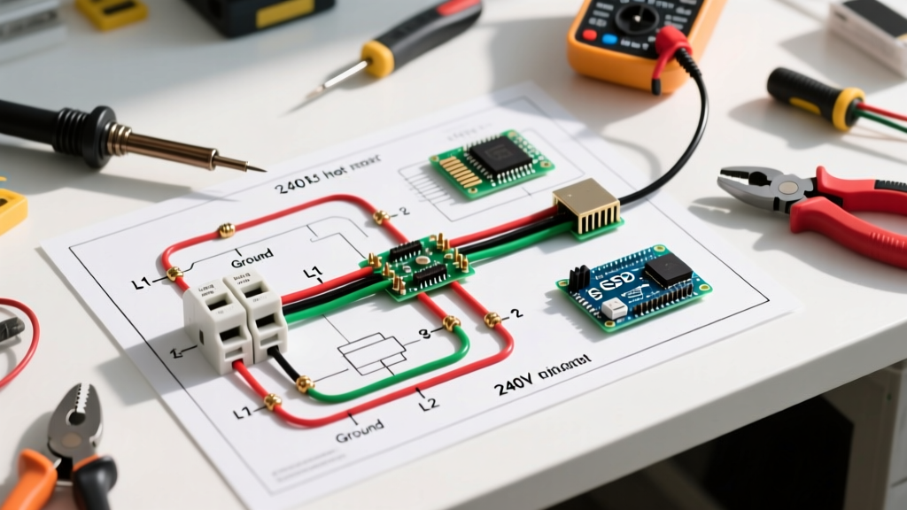
Upgrading, rewiring, or troubleshooting an electric vehicle is never as simple as connecting positive to positive. When you are working with a wiring diagram for EZ GO golf cart models, a meticulous installation planning phase is the difference between a reliable daily driver and a melted controller harness. Whether you are swapping a failing lead-acid battery bank for a modern 48V lithium setup, installing a high-speed motor, or adding accessory lighting, the electrical architecture of EZ GO vehicles demands strict adherence to factory schematics and updated safety standards.
In 2026, the aftermarket landscape for golf carts has shifted heavily toward lithium conversions and high-amperage AC drive systems. This guide serves as your comprehensive installation planning blueprint, breaking down platform identification, wire gauge mathematics, color-code decoding, and the critical edge cases that generic tutorials often miss.
Identifying Your EZ GO Platform Architecture
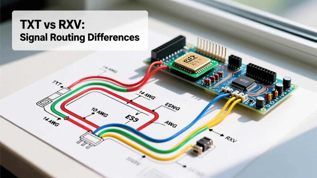
Before unrolling the schematic, you must definitively identify your cart's platform and drive system. EZ GO primarily utilizes two distinct chassis architectures, each with vastly different electrical topologies. Misidentifying your platform is the most common cause of controller blowouts during DIY installations.
| Feature | EZ GO TXT (1994–Present) | EZ GO RXV (2008–Present) |
|---|---|---|
| Drive Motor Type | DC Series or DCS (Separately Excited) | AC Induction Motor (Yamaha-designed) |
| Standard Voltage | 36V (Early) / 48V (PDS & Modern) | 48V (Standard across all years) |
| Braking System | Standard Mechanical Drum/Disc | Regenerative AC Braking (No rear brakes) |
| Controller Type | Curtis 1268 (PDS) or 1205 (Series) | Curtis 1352 or 1354 AC Controller |
| Wiring Complexity | Moderate (Accessible F&R switch, external solenoid) | High (Integrated CANbus, sealed AC harnesses) |
Decoding the EZ GO Harness Color Standards
While aftermarket harnesses can vary, factory OEM wiring diagrams for EZ GO golf carts rely on a specific color-code matrix. Memorizing or taping these references to your workbench will prevent catastrophic cross-wiring.
- Red (Heavy Gauge): Main Battery Positive (B+). Routes from the battery pack positive to the solenoid, and from the solenoid to the controller B+.
- Black (Heavy Gauge): Main Battery Negative (B-). Routes from the battery pack negative directly to the controller B-.
- Blue: Motor Field (F1/F2). Carries the electromagnetic field current. Swapping these reverses motor rotation.
- Yellow: Motor Armature (A1/A2). Carries the high-amperage rotational current.
- Green / White: Throttle and Microswitch signals. These are low-voltage signal wires (typically 12V-15V) originating from the ITS (Inductive Throttle Sensor) or V-Glide potentiometer.
- Orange: Key switch and accessory power feed (switched B+).
CRITICAL SAFETY DIRECTIVE: Always disconnect the main negative (Black) battery cable first, and reconnect it last. According to the NFPA 70 National Electrical Code guidelines for DC systems, interrupting the ground path first eliminates the risk of a dead-short if your wrench bridges the positive terminal to the cart's chassis during disassembly.
Wire Gauge Selection & Voltage Drop Calculations
A frequent failure mode in DIY golf cart builds is using undersized battery cables. A 48V EZ GO RXV pulling 300 amps during a steep hill climb will experience severe voltage drop if wired with standard 4 AWG automotive cable. Voltage drop manifests as controller low-voltage cut-offs and melted cable insulation.
When consulting your wiring diagram, use the following matrix to select the correct copper wire gauge based on your peak amperage draw and cable run length (round-trip distance).
| Wire Gauge (AWG) | Max Continuous Amps | Peak Amps (10 Sec) | Max Recommended Run (48V) | Typical Application |
|---|---|---|---|---|
| 2 AWG | 150A | 300A | 4 Feet | Main battery interconnects (Stock) |
| 1/0 AWG (1 AWG) | 200A | 400A | 6 Feet | High-speed motor / Lithium main leads |
| 2/0 AWG | 250A | 500A+ | 8 Feet | Heavy-duty competition / AC upgrades |
| 10 AWG | 30A | 45A | 10 Feet | Solenoid coil, voltage reducer inputs |
Pro Tip: Always use pure, tinned marine-grade copper wire (SAE J1127). Copper-clad aluminum (CCA) wire, often sold cheaply online, has 40% higher resistance and will overheat under the high-torque loads typical of golf cart applications.
The Solenoid Pre-Charge Circuit: An Often-Missed Edge Case
When tracing the wiring diagram for EZ GO golf cart solenoid circuits, many DIYers ignore the small gauge wires connected across the large solenoid terminals. This is the pre-charge resistor circuit (typically a 250-Ohm, 5-Watt ceramic resistor paired with a diode).
Why It Matters
The controller contains massive internal capacitors. When the solenoid slams shut, connecting a 48V pack directly to empty capacitors, it creates an instantaneous short circuit (inrush current can exceed 1,000 amps). This causes extreme arcing inside the solenoid, eventually pitting the copper contacts until they weld shut—leaving your cart stuck in the 'forward' position with no way to stop.
The Fix: The pre-charge resistor slowly trickles a small amount of current to fill the capacitors before the main solenoid contacts close. Never bypass this resistor when replacing a Curtis 70134G01 (48V) solenoid. If your cart has a clicking solenoid but no movement, test this resistor with a multimeter for continuity before condemning the controller.
Planning for 2026 Lithium Battery Conversions
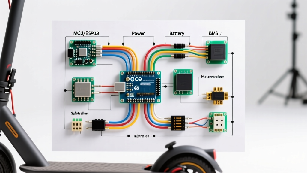
The most common reason enthusiasts pull up an EZ GO wiring diagram today is for a lead-acid to Lithium Iron Phosphate (LiFePO4) conversion. This requires specific planning deviations from the factory manual:
- OBC Bypass (TXT Models): Older TXT models use an On-Board Computer (OBC) to monitor individual 8V lead-acid cells. A single 48V lithium battery will confuse the OBC, causing it to shut off the charger. You must wire the charger receptacle directly to the main battery positive and negative terminals, completely bypassing the OBC's charge relay.
- Voltage Reducers: Never tap into a single 8V battery in a lead-acid bank to run 12V accessories (lights, radios). This unbalances the bank. For a 48V lithium setup, install a dedicated 48V-to-12V DC-DC step-down converter (minimum 15A / 180W). Wire the converter's input directly to the main pack B+ and B-, and fuse the 12V output side within 6 inches of the converter.
- Charger Receptacle Wiring: Use the manufacturer-provided communication harness. Modern 2026 lithium packs require a CANbus or RS485 handshake with the charger to dictate charge curves. Refer to the battery manufacturer's specific pinout diagram, as it will override the standard EZ GO 3-pin receptacle wiring.
For foundational knowledge on series and parallel battery bank wiring, the engineering manuals provided by Rolls Battery offer excellent visual references for maintaining balanced current flow across terminal connections, a principle that applies directly to the busbars on modern lithium drop-in replacements.
Step-by-Step Execution Strategy
Once your diagram is mapped and components are staged, follow this strict sequence to ensure a clean, hazard-free installation:
- Kill Power & Isolate: Turn the key off, set the F&R switch to Neutral, and engage the tow/run switch to 'Tow' (if equipped). Disconnect the main negative battery cable.
- Label and Photograph: Before removing a single wire from the controller or F&R switch, take high-resolution photos. Use blue painter's tape to label the Blue, Yellow, and Red motor/controller wires.
- Clean & Treat Terminals: Use a brass wire brush to clean all battery posts and controller studs. Apply a thin layer of dielectric grease after torquing the nuts to spec (typically 9-11 ft-lbs for 5/16" studs) to prevent galvanic corrosion.
- Wire the Control Circuit First: Connect the low-amperage signal wires (throttle, microswitches, key switch) to the controller before attaching the heavy high-voltage cables. This prevents accidental shorting while maneuvering bulky 1/0 AWG cables.
- Final Power-Up & Spark Test: Reconnect the main negative. A small, single 'tick' spark is normal (capacitors charging). A large, continuous spark indicates a dead short—immediately disconnect and re-check your solenoid and controller B- wiring.
Conclusion
Successfully executing a wiring diagram for EZ GO golf cart upgrades requires respecting the high-current DC environment these vehicles operate in. By accurately identifying your TXT or RXV platform, upsizing your battery cables to 1/0 AWG for modern loads, and respecting the pre-charge circuitry, you will build an electrical system that is both robust and safe for years of operation.