
Pre-Installation Planning and Load Calculation
Upgrading a classic vehicle to modern power windows, or replacing a failing OEM high-torque motor in a late-model truck, requires more than just splicing a few wires together. As of 2026, aftermarket high-torque window motors (such as the AutoLoc AWM2 or Dorman 905-515 direct replacements) routinely draw 15 to 20 amps during normal operation. However, the critical metric for your installation planning is the stall current—the amperage drawn when the glass reaches the top or bottom of its travel and the motor briefly locks. Stall currents can easily spike to 35 or 40 amps for 1.5 seconds.
If your wiring and switching topology cannot handle this transient spike, you will experience voltage drop, melted switch contacts, or nuisance fuse blows. Therefore, a robust wiring diagram for electric window switch integration must incorporate external relays to isolate the high-amperage motor circuit from the low-amperage dashboard switch. This guide details the industry-standard dual-relay H-bridge configuration, ensuring safe, reliable polarity reversal for your window motors.
Understanding Switch Topology: Direct vs. Relay-Triggered
Before cutting any wire, you must identify which switching topology your kit or vehicle requires. Direct-wiring is only suitable for low-draw, lightweight applications, whereas relay-triggered is mandatory for modern, heavy glass assemblies.
| Topology Type | Max Current Rating | Best Application | Failure Risk |
|---|---|---|---|
| Direct-Wire (3 or 5-Pin) | 15A - 20A | Lightweight classic cars, small quarter-windows | High (Contact arcing, melting) |
| Relay-Triggered (H-Bridge) | 30A - 40A+ | Heavy truck glass, modern restomods, EV conversions | Low (Isolated coil circuit) |
Executing the Wiring Diagram for Electric Window Switch Installs
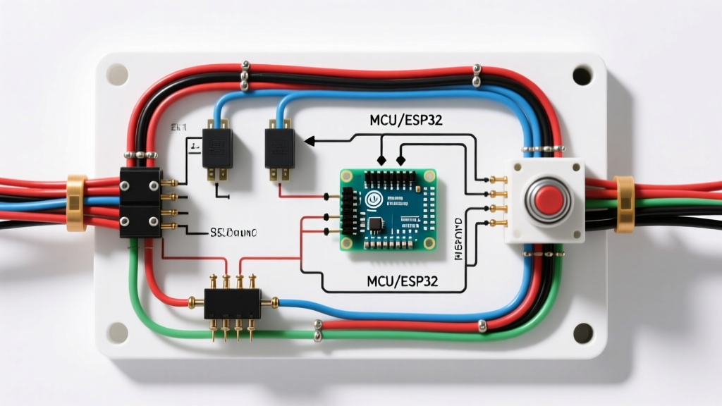
The gold standard for high-amperage polarity reversal is the Dual-Relay H-Bridge. This setup uses two standard Bosch-style 5-pin SPDT (Single Pole Double Throw) relays, such as the Bosch 0332014150. The dashboard switch only handles the low-current relay coil triggers (under 1A), while the relays handle the heavy 12 AWG motor feeds.
Step-by-Step H-Bridge Wiring Flow
- Primary Power Feed: Run a 10 AWG primary wire from the battery positive terminal to a 30A Slow-Blow (Time-Delay) ATO fuse holder. Mount the fuse within 18 inches of the battery. From the fuse, run 12 AWG wire to a central distribution block near the door harness.
- Relay Power (Pins 30 & 87): On both Relay A and Relay B, jumper Pin 30 to the 12V distribution block. Connect Pin 87 of Relay A to Motor Wire 1. Connect Pin 87 of Relay B to Motor Wire 2.
- Relay Ground (Pins 87a): Jumper Pin 87a of Relay A to Motor Wire 2. Jumper Pin 87a of Relay B to Motor Wire 1. This cross-wiring is what allows the polarity to flip depending on which relay is energized.
- Switch Triggers (Pins 85 & 86): Ground Pin 85 on both relays to a clean chassis ground. Connect Pin 86 of Relay A to Switch Terminal 'UP'. Connect Pin 86 of Relay B to Switch Terminal 'DOWN'. The center terminal of your DPDT dashboard switch receives a 16 AWG 12V ignition-switched feed.
Expert Note: Always use a Slow-Blow (Time-Delay) fuse rather than a Fast-Acting fuse for window motors. Fast-acting fuses will interpret the 1.5-second stall current spike as a dead short and blow prematurely. Refer to the Littelfuse Automotive Relay Application Guide for detailed inrush current tolerances.
Wire Gauge Selection and Voltage Drop Mitigation
Undersized wire is the leading cause of slow window operation. A motor receiving 10.5V instead of 12.5V will run 40% slower and generate excessive heat. When selecting your wire, you must adhere to the SAE J1128 standard for low-tension primary automotive cable, which accounts for the high-temperature environment inside door panels.
| Wire Gauge (AWG) | Max Run Length (One Way) | Max Continuous Amperage | Recommended Use Case |
|---|---|---|---|
| 16 AWG | 10 feet | 6A | Relay coil triggers, switch illumination |
| 14 AWG | 12 feet | 15A | Standard OEM replacement motors (low torque) |
| 12 AWG | 15 feet | 25A | High-torque aftermarket motors, H-Bridge feeds |
| 10 AWG | 20 feet | 35A | Main battery feed to distribution block |
Door Jamb Routing and Weatherproofing Standards
The transition from the vehicle chassis into the door panel is the most vulnerable point in any electric window circuit. The wires must flex thousands of times without fatiguing, while being completely shielded from rain, road salt, and car wash chemicals.
- Conduit Boots: Never run bare wires through the door hinge gap. Use a high-flex rubber conduit boot, such as the Dorman 86194 or OEM-equivalent weatherpack boots. Secure them with stainless steel hose clamps, not zip-ties, which degrade under UV and heat exposure.
- Wire Selection: Inside the door jamb boot, use SXL (Cross-Linked Polyethylene) or TXL automotive wire. These insulation types resist abrasion and handle temperatures up to 125°C, unlike cheap PVC wire which can melt if routed near aftermarket exhaust headers or door speakers.
- Terminations: Do not use solder inside the door panel. Soldered joints become brittle and crack under the constant vibration and flexing of a closing car door. Instead, use adhesive-lined heat shrink crimp connectors. The IWISS IWS-3220M crimping tool paired with 3M MDT heat shrink terminals provides a factory-grade, waterproof seal.
Diagnostic Edge Cases and Failure Modes
Even with a perfect wiring diagram for electric window switch layouts, environmental factors can introduce faults. When troubleshooting a newly installed system, avoid the trap of simply 'checking for 12V' with a test light. A test light draws minimal current and will illuminate even on a severely corroded wire that cannot power a motor.
The Voltage Drop Test Protocol
Use a True-RMS digital multimeter (such as the Fluke 87V) to perform a dynamic voltage drop test while the switch is held in the 'UP' position.
- Power Side Test: Place the red probe on the battery positive terminal and the black probe on the motor's positive input terminal. A healthy circuit should read less than 0.20V. If it reads 0.8V or higher, you have excessive resistance in the power feed, usually caused by undersized wire or a corroded relay Pin 30.
- Ground Side Test: Place the red probe on the motor's ground terminal and the black probe on the battery negative terminal. Again, the reading must be under 0.20V. High readings here indicate a poor chassis ground. Always sand the grounding point down to bare, shiny metal and apply a coating of Permatex 22058 dielectric grease to prevent future oxidation.
Common 2026 Installation Pitfalls
- Ignition vs. Constant 12V: Wiring the main power feed directly to the battery without an ignition-controlled master relay allows the window switches to remain 'hot' when the vehicle is parked. This is a severe fire hazard and a parasitic drain risk. Always use a secondary 40A master relay triggered by the ignition 'RUN' circuit to kill power to the window distribution block when the key is off.
- Binding Glass Tracks: If your electrical tests pass perfectly but the motor still trips the thermal breaker, the issue is mechanical. Dry, degraded window felts and tracks force the motor to work at stall-current continuously. Lubricate all glass run channels with a silicone-based dry lubricant (like 3M Silicone Spray) before finalizing the electrical diagnosis.
By treating the electrical installation as a complete system—calculating stall loads, utilizing an H-bridge relay topology, and adhering to strict weatherproofing standards—your power window upgrade will deliver OEM-level reliability for years to come.