
The Anatomy of a Craftsman 12V DC Electrical System
Whether you are restoring a vintage Sears garden tractor or maintaining a modern Craftsman T-series (like the T2200 or T3100), understanding the electrical schematic is critical for reliable operation. Unlike automotive systems that rely on complex CAN-bus networks, the wiring diagram for a Craftsman riding lawn mower utilizes a straightforward, low-voltage 12V DC architecture. However, the harsh operating environment—characterized by severe vibration, moisture, grass clippings, and extreme heat from the engine block—demands strict adherence to proper wire gauge selection and color-coding standards.
In this comprehensive reference guide, we break down the exact American Wire Gauge (AWG) specifications, industry-standard color codes, and diagnostic procedures required to trace, repair, and upgrade your mower's wiring harness. By mastering these fundamentals, you can eliminate the guesswork from electrical troubleshooting and prevent catastrophic short circuits.
Standard Wire Color Codes in Craftsman Mowers
While original equipment manufacturers (OEMs) like MTD and Husqvarna (who have manufactured Craftsman tractors in various eras) generally follow SAE International standards for low-tension primary cables, slight variations exist depending on the model year and engine manufacturer (Briggs & Stratton, Kohler, or Kawasaki). Below is the definitive color code matrix for modern Craftsman riding mowers.
| Wire Color | Primary Function | Typical Circuit Application |
|---|---|---|
| Red | Main Battery Positive (+) | Battery to starter solenoid, main ignition feed, alternator output. |
| Black | Ground / Negative (-) | Battery negative to chassis, engine block ground straps, PTO clutch ground. |
| Purple | Switched Ignition / PTO | Ignition switch 'A' terminal to PTO clutch relay, solenoid trigger wire. |
| White | Safety Interlock Loop | Seat switch, brake pedal switch, PTO engagement switch (normally closed/open loops). |
| Orange | Stator / Alternator AC Output | Engine stator to voltage regulator/rectifier (carries high-frequency AC before rectification). |
| Green | Lighting & Accessories | Headlights, taillights, dashboard illumination, 12V accessory ports. |
Pro-Tip for Restorers: On pre-2005 Craftsman models, you may encounter Yellow wires used for the stator AC output instead of Orange. Always verify with a multimeter set to AC Voltage (VAC) while the engine is running at 3,000 RPM; a healthy stator should output between 28VAC and 35VAC across these two wires before reaching the rectifier.
Wire Gauge (AWG) Selection by Circuit Load
Selecting the correct wire gauge is not merely about fitting the wire into a connector; it is about managing voltage drop and thermal limits. A standard riding mower features three distinct electrical tiers: high-current cranking, medium-current inductive loads, and low-current logic/lighting circuits.
1. High-Current Cranking Circuit (Starter & Battery)
The starter motor on a typical 19HP to 24HP Briggs & Stratton or Kohler engine can draw between 150 to 250 amps during initial cranking. To prevent severe voltage drop that starves the ignition module, the battery cables must be heavy-duty.
- Battery to Solenoid: 6 AWG (minimum 8 AWG for short runs under 24 inches).
- Solenoid to Starter Motor: 6 AWG stranded copper.
- Ground Strap (Engine to Chassis): 6 AWG braided copper or flat ground strap. Failure to maintain a clean, tight ground strap is the #1 cause of 'no-crank' conditions.
2. Medium-Circuit Inductive Loads (PTO Clutch & Fuel Solenoid)
The Power Take-Off (PTO) electromagnetic clutch is the most demanding accessory on the mower. A standard Warner Electric or Xtreme Torq PTO clutch draws 3.5A to 4.5A continuously at 12V DC. While 16 AWG could theoretically handle this amperage, the physical distance from the ignition switch to the front-mounted PTO clutch necessitates a thicker wire to prevent voltage drop.
- PTO Clutch Feed: 12 AWG or 14 AWG. (If voltage at the clutch connector drops below 10.5V under load, the clutch will slip, overheat, and burn out—a $250+ replacement mistake).
- Carburetor Fuel Shut-off Solenoid: 14 AWG (Draws ~1.5A).
3. Low-Current Logic, Interlocks, and Lighting
The safety interlock module, ignition switch logic, and LED/halogen lighting circuits draw minimal current but are highly sensitive to resistance caused by corrosion.
- Main Ignition Feed (Post-Fuse): 10 AWG or 12 AWG (Protected by a 20A or 30A inline blade fuse).
- Safety Switches (Seat/Brake): 16 AWG.
- Lighting Circuits: 16 AWG or 18 AWG.
Tracing the Schematic: From Battery to PTO Engagement
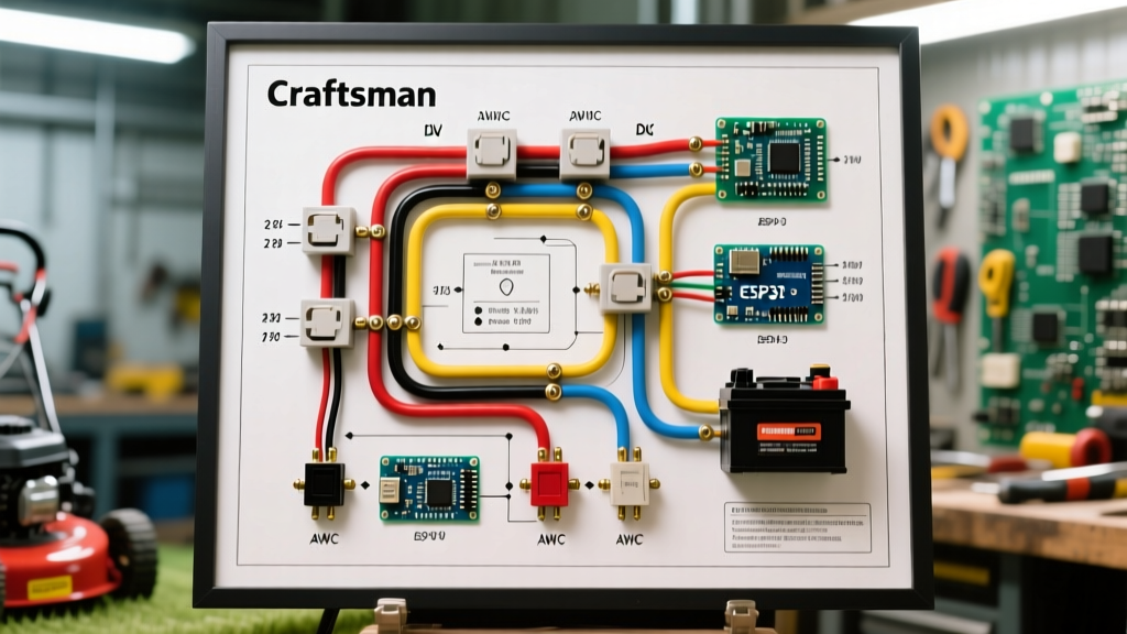
When reading the wiring diagram for a Craftsman riding lawn mower, it is best to trace the current flow sequentially. Here is the exact path the electrical current takes when you turn the key and engage the mower deck.
- Main Power Feed: 12V DC leaves the positive battery terminal via a 6 AWG red cable, terminating at the 'B' (Battery) post of the starter solenoid.
- Fused Ignition Feed: A secondary 12 AWG red wire branches off the solenoid 'B' post (or directly from the battery), passing through a 20A inline fuse, and connects to the 'B' terminal on the ignition switch.
- Key to 'Run': Turning the key to 'Run' bridges the 'B' terminal to the 'A' (Accessory/Ignition) terminal. This sends 12V down a purple wire to the PTO switch and the safety interlock module.
- The Interlock Logic Gate: Before the PTO can engage, the interlock module checks the status of the brake pedal switch (must be depressed) and the seat switch (must be occupied, or PTO must be disengaged). If conditions are met, the white interlock wires complete the circuit, allowing the purple wire to energize the PTO relay.
- PTO Engagement: The relay closes, sending full battery voltage directly to the PTO clutch via a heavy 12 AWG wire, engaging the magnetic friction disc and spinning the mower deck blades.
Real-World Failure Modes & Multimeter Diagnostics
Electrical faults on riding mowers rarely manifest as a simple 'broken wire.' The combination of vibration and environmental debris creates specific, repeatable failure modes. Use a digital multimeter (DMM) to diagnose these common issues.
Failure Mode 1: The Melted PTO Connector
Symptom: The mower deck engages sporadically, or the PTO clutch gets excessively hot. You notice a burnt plastic smell near the front of the chassis.
Root Cause: The spade connectors on the PTO clutch oxidize over time due to exposure to rain and grass acidity. This oxidation increases electrical resistance. According to Ohm's Law (V=IR), increased resistance at a constant amperage draw generates excessive heat, eventually melting the plastic connector housing.
The Fix: Cut off the melted OEM spade connectors. Strip the wire back to clean copper, and crimp on new nickel-plated female spade connectors with heat-shrink tubing. Apply a dab of dielectric grease to prevent future corrosion.
Failure Mode 2: Ghost Kill Switch (Engine Dies When PTO Engages)
Symptom: The engine runs perfectly until you pull the PTO lever, at which point the engine instantly shuts off.
Root Cause: This is a classic safety interlock failure. The interlock module is designed to ground the ignition coil (killing the engine) if the operator leaves the seat while the PTO is engaged. If the seat switch micro-switch fails internally, or if the wiring harness chafes against the seat spring and grounds out, the module 'thinks' the seat is empty.
The Fix: Disconnect the seat switch harness. Use your DMM set to continuity (Ohms). Sit on the seat and probe the switch terminals. It should show near 0 ohms (closed). If it shows infinite resistance (open) while seated, replace the switch. OEM Craftsman seat switches typically cost between $15 and $28 in 2026.
Failure Mode 3: Battery Not Charging (Stator vs. Regulator)
Symptom: The battery dies after 2 hours of mowing, even with a new battery.
Root Cause: Either the engine stator is failing to generate AC voltage, or the voltage regulator/rectifier is failing to convert it to 13.8V-14.2V DC.
The Fix: Unplug the regulator. Start the engine and run at full throttle. Probe the two stator wires (usually orange or yellow) with your DMM set to VAC. If you read 28V to 35V AC, the stator is healthy, and the voltage regulator is defective. If you read 0V to 5V AC, the stator windings under the engine flywheel are burnt out and require flywheel removal and stator replacement. Refer to the Briggs & Stratton official repair manuals for specific flywheel torque specs during reassembly.
Harness Repair: Upgrading for Longevity
When repairing the wiring diagram for a Craftsman riding lawn mower, avoid the temptation to use cheap twist-on wire nuts or standard vinyl electrical tape. The engine vibration will shake wire nuts loose within a single mowing season, and vinyl tape adhesive turns into a messy sludge when exposed to 140°F engine bay temperatures.
- Use Adhesive-Lined Heat Shrink: When splicing wires, use marine-grade heat shrink tubing with an inner layer of thermoplastic adhesive. When heated, the adhesive melts and seals the connection against moisture ingress.
- Deutsch Connectors for High-Vibration Zones: For connections near the engine block or the PTO clutch, upgrade from standard spade terminals to 2-pin Deutsch DT connectors. These feature silicone seals and lock into place, making them impervious to vibration and water.
- Corrugated Loom and Zip Ties: Always route repaired wires through split-loom tubing. Secure the loom to the chassis using UV-resistant zip ties, ensuring the harness does not rest against the exhaust manifold or the sharp edges of the steering column.
Replacing an entire OEM wiring harness for a Craftsman T2200 or similar model can cost upwards of $110 to $160 for the part alone, not including the 3-4 hours of labor required to strip the tractor down to route it. By understanding wire gauges, color codes, and proper splicing techniques, you can perform targeted, permanent repairs for under $20 in materials, keeping your tractor running reliably for years to come.