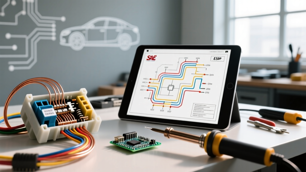

The Hidden Dangers of Misreading Automotive Schematics
Learning how to read car electrical wiring diagrams is often treated as a simple exercise in matching colors and symbols. However, from a safety and code compliance perspective, a wiring diagram is a critical blueprint that dictates fire prevention, module protection, and occupant safety. As of 2026, with the widespread integration of 48V mild-hybrid architectures, CAN-FD networks, and 800V EV platforms, misinterpreting a schematic isn't just about blowing a fuse—it can result in catastrophic arc flashes, destruction of a $2,500 Battery Management System (BMS), or accidental deployment of pyrotechnic safety devices.
This guide strips away the basics and focuses on the safety-critical aspects of reading automotive wiring diagrams, ensuring your modifications comply with SAE International Standards and prevent hazardous electrical failures.
Decoding Safety-Critical Symbols and Topologies
Standard automotive diagrams use a specific lexicon to denote components. While you likely know the symbols for a battery or a switch, safety compliance requires strict attention to protective topologies.
- Splice Packs (S100, S205): These indicate factory-joined wire harnesses. Safety Rule: Never tap into a splice pack for aftermarket accessories. Doing so alters the voltage drop and can starve OEM sensors, leading to erratic ECU behavior.
- Ground Distribution (G101, G204): Factory grounds are strictly mapped. A diagram will show multiple components sharing a single ground point. Safety Rule: Never add high-current aftermarket loads (like amplifiers or winches) to an ECU or sensor ground node. This induces ground-loop voltage spikes that can fry sensitive logic boards.
- Shielded Wires (Dashed Lines or 'SHLD' notation): Used for high-speed CAN-bus, audio, and crankshaft position sensors. Safety Rule: Never splice into shielded wires without properly terminating the drain wire to ground, otherwise electromagnetic interference (EMI) will corrupt safety-critical data like ABS braking signals.
⚠️ CRITICAL SAFETY WARNING: Never use a standard incandescent test light to probe circuits marked with SRS (Airbag), Pre-Tensioner, or Pyrotechnic symbols on the diagram. The low resistance of the test light filament can draw enough current to accidentally deploy an airbag module. Always use a high-impedance Digital Multimeter (DMM) with an impedance greater than 10 Mega-ohms.
Wire Insulation Standards: SAE J1128 vs. Generic PVC
When a diagram specifies a wire gauge, it implicitly relies on automotive temperature standards. A common and highly dangerous code violation is using standard building wire (THHN/THWN) or cheap PVC primary wire for under-hood automotive modifications.
Automotive wiring must comply with SAE J1128 specifications, which dictate cross-linked polyethylene (XLPE) insulation capable of withstanding severe under-hood environments.
| Wire Type | Insulation Material | Max Temp Rating | Wall Thickness | Compliance & Use Case |
|---|---|---|---|---|
| SXL | Cross-Linked (XLPE) | 125°C (257°F) | Thick | High-heat zones (near exhaust manifolds) |
| GXL | Cross-Linked (XLPE) | 125°C (257°F) | Thin | Standard under-hood OEM routing |
| TXL | Cross-Linked (XLPE) | 125°C (257°F) | Extra Thin | Modern harnesses, tight conduit spaces |
| PVC (Generic) | Polyvinyl Chloride | 90°C (194°F) | Variable | VIOLATION: Melts/degrades in engine bays |
Step-by-Step: Tracing a Circuit for Safe Accessory Integration
When adding an accessory (e.g., LED light bars, auxiliary fuel pumps), you must trace the diagram to find a safe ignition-switched power source without overloading OEM circuits. Follow this exact methodology:
- Locate the Fuse Block Topology: Identify the specific fuse block (e.g., 'Underhood Bussed Electrical Center - UBEC'). Note the main feed amperage. If the UBEC is fed by a 60A J-Case fuse, the sum of all downstream circuits cannot exceed 80% of that capacity (48A) for continuous loads, per NFPA electrical safety guidelines adapted for mobile platforms.
- Identify the Run Relay: Do not tap directly into a low-current control wire. Look for the 'Run/Crank' relay output on the diagram. This ensures your accessory only powers when the ignition is in the 'ON' position, preventing parasitic battery drain.
- Verify Wire Gauge Capacity: If the diagram shows a 16 AWG wire protected by a 15A MINI fuse, you cannot safely tap into this wire to draw an additional 10A. The 15A fuse will not blow until the wire reaches its thermal melting point, creating a severe fire hazard. Instead, use the diagram to locate an empty, pre-wired 'upfitter' or 'auxiliary' switched relay cavity.
- Map the Ground Path: Trace the ground path on the diagram to a dedicated chassis stud (usually denoted by a heavy black line and a bolt symbol). Clean the metal to bare steel using a wire brush and apply dielectric grease after torquing to spec.
Common Code Violations in Automotive Aftermarket Wiring
Even experienced DIYers make critical errors when interpreting complex modern schematics. Avoid these severe safety violations:
1. Tapping into CAN-Bus Networks
Modern diagrams show CAN-High and CAN-Low twisted pair networks. Tapping into these wires to 'read' vehicle speed or RPM data without a proper galvanic isolation module can introduce voltage spikes. If you back-feed 12V into a CAN line operating at 2.5V, you will instantly destroy the gateway module and immobilize the vehicle.
2. Ignoring 'Smart' Alternator Topologies
In 2026, most vehicles utilize LIN-bus controlled 'smart' alternators that vary output voltage between 12.2V and 14.8V based on battery state-of-charge (SoC). If you read the diagram and connect a high-draw aftermarket inverter directly to the battery without integrating a battery isolator or a DC-DC charger, the vehicle's BMS will misinterpret the parasitic draw, potentially overcharging or undercharging the primary lithium-ion or AGM battery.
3. Using Improper Connectors
Schematics often denote sealed connections. Using standard vinyl crimp butt-splices in the engine bay violates moisture ingress standards. Always use adhesive-lined heat shrink and sealed connector systems like the Deutsch DT series or Weather-Pack for under-hood splices.
Essential Diagnostic Tools for Safe Verification
Reading the diagram is only half the battle; verifying the physical circuit matches the schematic safely requires the right tools. According to Fluke Electrical Testing Guidelines, using the correct category-rated meter is non-negotiable.
- High-Impedance DMM (e.g., Fluke 87V or Innova 5610): Essential for probing ECU, sensor, and airbag circuits without drawing current. Expect to invest $250 - $450 for a reliable, automotive-rated unit.
- Logic Probe / Power Probe (e.g., Power Probe IV): Excellent for verifying power and ground at heavy-current nodes (headlights, fuel pumps) without the risk of back-probing and bending delicate terminal pins. ($200 - $300 range).
- Current Clamp (Hall Effect): Allows you to measure the actual amperage draw of a circuit against the diagram's specifications without piercing the wire insulation, which compromises the wire's moisture resistance.
Final Thoughts on Compliance and Safety
Mastering how to read car electrical wiring diagrams is an exercise in risk management. By respecting SAE wire temperature ratings, honoring OEM ground topologies, and utilizing high-impedance testing equipment, you ensure that your vehicle modifications remain safe, reliable, and compliant with automotive engineering standards. Never guess when a schematic is unclear; consult the factory service manual (FSM) and verify with a multimeter before making a single cut.