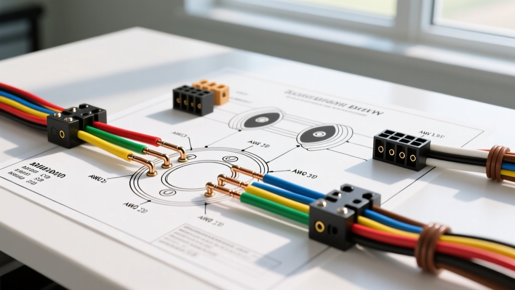

The Critical Role of Wire Gauge in Trailer Brake Circuits
When pulling a loaded car hauler, travel trailer, or flatbed, the stopping power of your rig relies entirely on the integrity of the electrical connection between the tow vehicle and the trailer. While modern 2026 brake controllers like the Redarc Tow-Pro Elite or Curt Spectrum utilize advanced Pulse Width Modulation (PWM) to deliver smooth, proportional braking, they are completely at the mercy of your physical wiring. Consulting a standard wiring diagram for trailer with electric brakes is only the first step; understanding the underlying wire gauge requirements and RVIA color codes is what prevents catastrophic voltage drop and brake fade on steep downgrades.
Electric trailer brakes operate on a simple 12-volt DC electromagnetic principle. When the brake controller sends a signal, an electromagnet inside the brake drum expands against the drum surface, actuating the brake shoes. However, these magnets draw significant current—often between 3 to 4 amps per wheel. On a dual-axle trailer, a hard stop can pull 12 to 16 amps through the main brake wire. If your wire gauge is undersized, resistance increases, voltage drops, and your brakes physically lose clamping force.
The 7-Way RV Blade Standard (SAE J286)
The 7-way RV blade connector is the undisputed standard for trailers equipped with electric brakes in North America. Governed by SAE J286 and RVIA (Recreation Vehicle Industry Association) guidelines, this connector separates the high-current braking and charging circuits from the low-current lighting circuits. Below is the industry-standard pinout and color code matrix.
| Pin Position | Function | RVIA Standard Color | Minimum AWG (Gauge) | Wire Type Recommendation |
|---|---|---|---|---|
| 1 (Ground) | Chassis Ground | White | 10 AWG or 8 AWG | SAE J1128 SXL |
| 2 (Tail) | Tail / Running Lights | Brown | 16 AWG (LED) / 14 AWG | SAE J1128 GXL |
| 3 (Left) | Left Turn / Stop | Yellow | 16 AWG (LED) / 14 AWG | SAE J1128 GXL |
| 4 (Aux) | 12V Aux / Battery Charge | Black | 10 AWG | SAE J1128 SXL |
| 5 (Right) | Right Turn / Stop | Green | 16 AWG (LED) / 14 AWG | SAE J1128 GXL |
| 6 (Brakes) | Electric Brakes | Blue | 10 AWG | SAE J1128 SXL |
| 7 (Backup) | Backup Lights / Reverse Lockout | Red or Purple | 14 AWG | SAE J1128 GXL |
A Warning on Manufacturer Color Deviations
While the RVIA standard dictates the colors above, many utility trailer manufacturers and overseas importers use non-standard color codes to cut costs. According to the etrailer RV Wiring FAQ, it is incredibly common to find bare copper wires, or completely randomized colors on cheaper flatbed trailers. Never trust the jacket color blindly. Always use a multimeter to trace continuity from the 7-way plug to the specific axle component before splicing into your tow vehicle's harness.
Wire Gauge Sizing and the Voltage Drop Hazard
The most common mistake DIYers make when wiring a trailer with electric brakes is using 12 AWG or 14 AWG wire for the blue brake circuit to save money. This is a severe safety hazard. To understand why, we must look at the voltage drop formula:
Voltage Drop Formula:
V_drop = (2 × L × I × R) / 1000
Where L = one-way wire length in feet, I = current in amps, and R = wire resistance per 1,000 feet.
Let us calculate a real-world scenario for a 24-foot car hauler. The one-way run from the 7-way connector to the rear axle is roughly 28 feet. During an emergency stop, the brake controller commands maximum output, drawing 15 amps across four brake magnets.
- Using 10 AWG Wire (R = 1.018 Ω/kft): The voltage drop is 0.85V. Your brakes receive 11.15V, providing 100% of their rated stopping torque.
- Using 14 AWG Wire (R = 2.525 Ω/kft): The voltage drop is 2.12V. Your brakes receive only 9.88V. Because electromagnetic force is highly sensitive to voltage, this 18% drop in voltage can result in a 30% to 40% loss in actual braking torque, drastically increasing your stopping distance.
For comprehensive resistance data across all gauges, the Engineering Toolbox AWG Reference remains the definitive engineering standard. Always size your blue brake wire and white ground wire to a minimum of 10 AWG for any trailer exceeding 15 feet in length.
Choosing the Right Wire Insulation: SAE J1128 vs. THHN
Another critical failure point in trailer wiring is the insulation type. Many hardware stores sell THHN (Thermoplastic High Heat-resistant Nylon-coated) building wire. Never use THHN for trailer chassis wiring. THHN is designed for static, indoor conduit runs. The nylon jacket becomes brittle under UV exposure and will shatter under the constant high-frequency vibration of a moving trailer, leading to short circuits against the steel frame.
Instead, you must use automotive-grade wire that meets SAE J1128 standards. Look for these specific designations:
- GXL (General Cross-Linked): Standard automotive wire, rated to 125°C. Excellent for lighting circuits.
- SXL (Special Cross-Linked): Features a thicker insulation jacket. Highly resistant to abrasion, heat, and chemicals. This is the mandatory choice for the 10 AWG brake and ground circuits routed along the trailer's steel I-beams.
- TXL (Thin-wall Cross-Linked): Thinner insulation for tight spaces, but less abrasion-resistant. Avoid for exposed chassis runs.
Routing the Breakaway Switch Circuit
A wiring diagram for trailer with electric brakes is incomplete without the breakaway system. Federal and state laws require trailers with brakes to have a breakaway switch that applies full 12V battery power to the brakes if the trailer detaches from the hitch.
Step-by-Step Breakaway Wiring
- Power Source: Wire the breakaway switch directly to the dedicated breakaway battery (usually a 12V 5Ah SLA battery) or the 12V Aux (Black) wire coming from the 7-way plug. Do not splice into the brake controller's output wire.
- Output Splice: The output wire from the breakaway switch must be spliced into the Blue (Electric Brake) wire on the trailer side of the 7-way connector.
- Diode Protection (Optional but Recommended): In 2026, many advanced PWM brake controllers can be damaged by back-fed voltage from the breakaway battery. Installing a 15-amp blocking diode on the blue wire between the 7-way plug and the breakaway splice prevents reverse current from frying your tow vehicle's brake controller module.
Common Failure Modes and Edge Cases
Even with the correct wiring diagram and gauge, trailers experience specific electrical failures. Here is how to troubleshoot the most common edge cases:
1. The 'Phantom' Ground Failure
Many DIYers rely on the physical connection between the hitch ball and the coupler to complete the ground circuit for the trailer lights and brakes. This is a massive mistake. Rust, paint, and grease on the hitch ball create high resistance. The white ground wire from the 7-way plug must be ring-terminated and bolted directly to the trailer's bare steel frame using a star washer to bite through the paint. For aluminum trailers, you must run a dedicated copper ground wire all the way to the axle mounting plates, as aluminum oxide acts as an insulator.
2. PWM Controller Error Codes
Modern proportional brake controllers monitor the impedance of the brake circuit. If you use undersized wire, or if a ground connection is slightly corroded, the controller will read the higher resistance as an 'Open Circuit' or 'Short Circuit' and throw an error code on the dashboard, refusing to send power to the brakes. Upgrading the white ground wire to 8 AWG and cleaning all frame contact points with a wire brush and dielectric grease usually resolves these phantom errors.
3. Heat Shrink vs. Electrical Tape
Standard vinyl electrical tape will unspool within a single summer season due to heat and road grime. Every splice on a trailer chassis must be sealed using adhesive-lined marine-grade heat shrink tubing. When heated, the inner adhesive melts and forms a waterproof seal, preventing capillary action from drawing moisture into the copper strands, which causes internal green corrosion (copper oxide) that increases resistance over time.
Final Inspection Checklist
Before hitting the road, verify your setup against the RVIA ANSI Standards for low-voltage systems. Ensure your 10 AWG blue and white wires are secured in split-loom tubing where they pass through metal cross-members to prevent chafing. Test the breakaway switch by pulling the pin and verifying that the trailer wheels lock up completely when spun by hand. Proper wire gauge selection and meticulous termination are the only ways to guarantee your electric brakes will perform when you need them most.