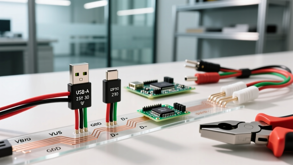

The Evolution of USB Charging: From 500mA to 240W
Understanding a USB wiring diagram for charging is no longer just about connecting a red and black wire to a 5V source. As of 2026, the universal serial bus ecosystem has evolved from a simple 5V/500mA data interface into a complex, high-power delivery network capable of pushing 240W (48V/5A) under the USB Power Delivery (PD) 3.1 Extended Power Range (EPR) specification. Whether you are designing a custom 12V-to-USB-C panel mount for a camper van, repairing a proprietary charging cable, or troubleshooting voltage drop issues in a DIY power bank, mastering the physical pinouts and negotiation protocols is mandatory.
This guide breaks down the exact wiring schematics for legacy USB-A/Micro-B charging and the highly complex USB-C architecture, providing actionable electrical data for DIYers and engineers.
Standard USB-A and Micro-B Wiring Diagram (USB 2.0)
The classic USB 2.0 wiring diagram relies on a simple 4-pin configuration. While largely superseded by USB-C in modern consumer electronics, USB-A remains heavily used in automotive dashboards, budget solar charge controllers, and legacy industrial equipment.
Wire Color Codes and Pin Functions
| Pin | Standard Color | Function | Electrical Characteristics |
|---|---|---|---|
| 1 | Red | VBUS (Power) | +5V DC (±5%) |
| 2 | White | D- (Data Minus) | Data / Charging Handshake |
| 3 | Green | D+ (Data Plus) | Data / Charging Handshake |
| 4 | Black | GND (Ground) | 0V Reference |
The Battery Charging (BC 1.2) Handshake
If you simply wire VBUS and GND to a device and leave D+ and D- floating, the device will default to the standard USB 2.0 specification and draw a maximum of 500mA. To unlock higher charging currents (1.0A to 1.5A), the USB Battery Charging 1.2 (BC 1.2) specification utilizes the data lines for hardware identification.
- Dedicated Charging Port (DCP): To signal a device that it is connected to a wall charger (not a PC), D+ and D- must be shorted together at the source connector. This tells the sink device it can safely draw up to 1.5A.
- Proprietary Dividers (Legacy Apple/Samsung): Older devices used specific voltage dividers on the data lines. For example, a standard 1A Apple charging configuration required pulling both D+ and D+ to 5V via 51kΩ resistors. A 2.1A configuration required D+ pulled to 5V via 51kΩ and D- pulled to GND via 51kΩ.
Advanced USB-C Wiring Diagram and Power Delivery (PD)
USB Type-C abandons the simple 4-pin layout for a 24-pin reversible connector. When analyzing a USB-C wiring diagram for charging, the focus shifts from the data lines to the Configuration Channel (CC) pins and the VBUS architecture.
Crucial USB-C Power Pins
- VBUS (4 pins): Carries the actual charging power. In high-current 5A cables, these pins are internally paralleled to reduce resistance and heat.
- GND (4 pins): The return path, also paralleled for high-current capacity.
- CC1 and CC2 (Configuration Channel): The brain of USB-C. These pins handle power role negotiation, cable orientation detection, and PD messaging.
- VCONN: Provides 5V power to the E-Marker chip embedded inside high-power USB-C cables.
The 5.1kΩ Pull-Down Resistor Rule
A common mistake in DIY USB-C wiring is omitting the pull-down resistors. If you are wiring a USB-C receptacle to act as a power sink (a device receiving charge), you must install a 5.1kΩ pull-down resistor from both CC1 and CC2 to GND. Without these resistors, a modern USB-C PD power supply will not output any voltage on VBUS, as it assumes no device is connected. For a deep dive into CC pin logic, refer to the SparkFun USB-C CC Pins Tutorial.
USB-C Power Delivery (PD) 3.1 and E-Marker Wiring
With the widespread adoption of USB PD 3.1 in 2026, charging laptops, power tools, and e-bikes at 140W to 240W requires the cable to negotiate the Extended Power Range (EPR). This is where the VCONN pin becomes critical.
Expert Warning: Never attempt to wire a custom 100W+ USB-C cable without integrating an E-Marker chip. The USB Implementers Forum (USB-IF) mandates that any cable rated for 5A or EPR voltages (28V/36V/48V) must contain an E-Marker on the VCONN line to authenticate its current-carrying capacity to the power source.
When wiring a USB-C plug for high-power applications, the VCONN pin must be routed to the VCC pin of the E-Marker IC (such as the Cypress CYPD3177). The source provides 5V on VCONN to power this chip, reads its I2C data, and only then enables the high-voltage VBUS MOSFETs.
Step-by-Step: Wiring a Custom 12V-to-USB-C PD Panel Mount
For automotive, marine, or off-grid solar setups, converting a 12V-24V battery bank into a fast-charging USB-C PD port requires a specialized trigger/buck module. Here is how to wire it safely.
Required Components
- PD Trigger/Buck Module: e.g., IP2721 or STUSB4500-based board (rated for 60W+).
- USB-C Receptacle: 16-pin or 24-pin mid-mount SMD or through-hole.
- Wire: 18 AWG for main power input, 20 AWG for VBUS output.
- Fusing: Inline automotive blade fuse (5A for 60W at 12V).
Wiring Procedure
- Input Power: Connect your 12V/24V source to the VIN+ and VIN- pads of the buck module. Ensure the inline fuse is placed on the positive lead within 6 inches of the battery terminal.
- CC Pin Configuration: The PD module will have pads labeled CC1 and CC2. Wire these directly to the CC1 and CC2 pins on your USB-C receptacle. Solder the 5.1kΩ pull-down resistors here if the module does not have them pre-populated.
- VBUS and GND: Connect the VOUT+ of the module to the 4 VBUS pins on the receptacle. Connect VOUT- to the 4 GND pins. Use a generous amount of 63/37 rosin-core solder and verify continuity with a multimeter to ensure no bridging between VBUS and CC pins.
- Data Lines (Optional): If this is strictly for charging, leave the TX/RX and D+/D- pins unconnected. This physically prevents data transfer, acting as a hardware-level security measure against 'juice jacking' in public or shared spaces.
Troubleshooting: Voltage Drop and Wire Gauge Selection
The most frequent cause of DIY USB charging failure is excessive voltage drop due to undersized wiring. USB devices are highly sensitive to VBUS voltage. The USB PD specification allows for a maximum voltage drop across the cable and connectors, but standard 5V charging requires the device to see at least 4.75V at the plug.
The AWG Math for USB Charging
Standard 24 AWG copper wire has a resistance of approximately 25.67 Ω per 1,000 feet. If you use a 6-foot cable (12 feet total round-trip for VBUS and GND), the resistance is roughly 0.308 Ω.
- At 1A (5W): Voltage drop = 1A × 0.308Ω = 0.308V. (Device sees 4.69V - borderline, may charge slowly).
- At 3A (15W): Voltage drop = 3A × 0.308Ω = 0.924V. (Device sees 4.07V - charging will halt completely).
Solution: For any custom USB wiring exceeding 3 feet, upgrade the VBUS and GND lines to 20 AWG (10.15 Ω/1000ft) or 18 AWG (6.38 Ω/1000ft). Always refer to standard UL cable safety guidelines to ensure your wire insulation can handle the thermal load of high-current PD charging without melting.
Frequently Asked Questions
Can I wire a USB-A port directly to a 5V lithium battery?
No. A raw lithium-ion cell ranges from 4.2V (fully charged) down to 3.0V (empty). Most USB devices will reject 4.2V as it exceeds the 5% tolerance of the 5V spec, and will shut off at 4.5V. You must use a 5V boost converter (like the MT3608 or TPS61023) between the battery and the USB VBUS pin.
Why does my custom USB-C cable only charge at 60W instead of 100W?
Standard USB-C cables without an E-Marker chip are hardware-limited by the PD specification to 3A. At 20V, 3A equals 60W. To achieve 100W (20V/5A), your wiring diagram must include an E-Marker chip powered via the VCONN pin to authenticate the 5A capability to the charger.