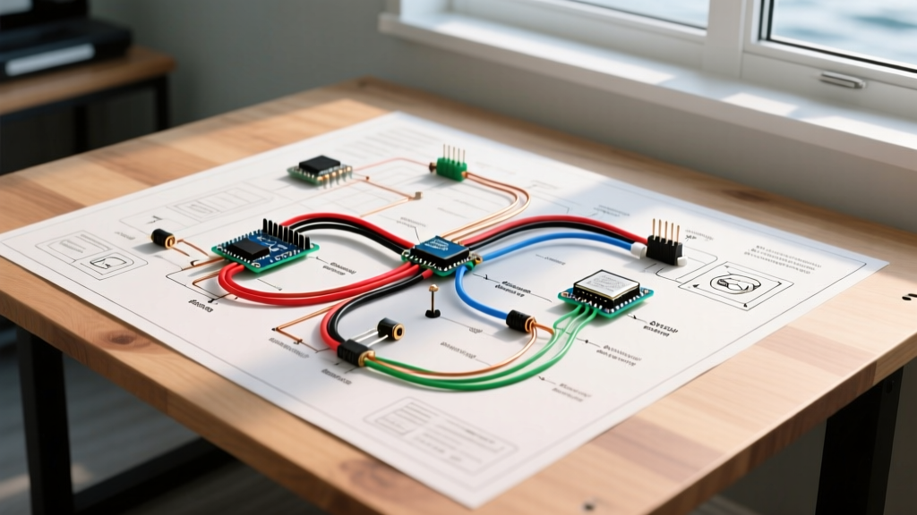

Why a Custom Wiring Diagram for a Boat is Non-Negotiable
Unlike automotive or residential electrical systems, the marine environment is relentlessly hostile to electronics. Constant vibration, high humidity, and salt-laden air can turn a poorly planned DC system into a fire hazard or a source of catastrophic stray-current corrosion. Creating a comprehensive wiring diagram for a boat is not just an organizational exercise; it is a critical safety requirement governed by the American Boat & Yacht Council (ABYC) E-11 standards.
In this step-by-step walkthrough, we will guide you through engineering, drafting, and executing a custom marine DC wiring diagram. Whether you are refitting a 24-foot center console or upgrading the house bank on a 40-foot cruiser, this guide provides the exact specifications, material costs (updated for 2026), and technical frameworks you need to build a resilient marine electrical system.
Expert Insight: According to the ABYC E-11 Standards, every ungrounded current-carrying conductor on a vessel must be protected by an overcurrent device (fuse or circuit breaker) within 7 inches of the power source. A precise wiring diagram ensures you never miss a protection point during installation.
Step 1: Calculate Your DC Load Matrix
Before drawing a single line on your schematic, you must quantify your electrical demands. A wiring diagram for a boat is only as good as the data feeding it. Create a DC Load Matrix that accounts for the maximum continuous amperage of every device on board.
Typical Marine DC Load Matrix (12V System)
| Component | Max Amp Draw | Wire Gauge (AWG) | Breaker/Fuse Size | Estimated 2026 Cost |
|---|---|---|---|---|
| Rule 2000 Bilge Pump | 8.0A | 14 AWG | 10A Blade Fuse | $45 (Pump + Wire) |
| VHF Radio (Transmitting) | 6.0A | 14 AWG | 10A Blade Fuse | $25 (Wire + Terminals) |
| Chartplotter (12-inch) | 3.5A | 16 AWG | 5A Blade Fuse | $20 (Wire + Terminals) |
| LED Nav/Anchor Lights | 1.5A | 16 AWG | 3A Blade Fuse | $30 (Wire + Terminals) |
| Vertical Windlass | 85.0A | 2/0 AWG | 100A ANL Fuse | $280 (Heavy Cable + Lugs) |
Note: Wire gauges listed assume a maximum 15-foot one-way run from the distribution panel. Always adjust for voltage drop on longer runs.
Step 2: Map the ABYC Color Codes and Symbols
Standardizing your color codes prevents fatal troubleshooting errors years down the line. When drafting your wiring diagram for a boat, use standard electrical symbols (e.g., zigzag for resistors, parallel lines for batteries) and strictly adhere to ABYC color designations for DC systems.
ABYC DC Color Code Standards
- Yellow: DC Grounding / Negative Return (Most common in modern marine systems to avoid confusion with AC hot wires).
- Yellow with Red Stripe: DC Starting Circuit (Starter motor positive).
- Red: DC Ungrounded / Positive (Used for general distribution, though many modern boat builders use red for positive and yellow for negative universally).
- Black: AC Grounding or Shielding (Never use black for DC negative on a boat, as it mimics AC hot and causes dangerous confusion).
- Orange: Distributor to ignition coil / alternator control circuits.
Step 3: Draft the Schematic Layout
With your load matrix and color codes established, it is time to draw the actual wiring diagram for a boat. You can use CAD software like AutoCAD Electrical, marine-specific tools like BoatCad, or simply draft it by hand on marine-grade vellum paper.
Topological Best Practices for Marine DC
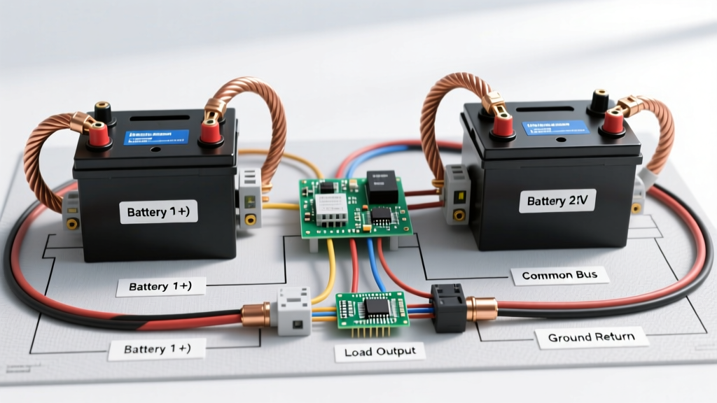
- Centralized Busbars: Do not daisy-chain negative wires. Route all DC negative returns to a centralized, insulated negative busbar (e.g., Blue Sea Systems 250A Common 1502). This creates a clean star-ground topology, minimizing ground loops and radio frequency interference (RFI) in your VHF and AIS systems.
- Distribution Panels: Route all positive feeds through a primary DC distribution panel equipped with magnetic hydraulic circuit breakers. Thermal breakers are prone to nuisance tripping in hot engine rooms.
- Fuse Placement: On your diagram, explicitly mark the location of the main battery fuse. The Blue Sea Systems Circuit Protection Guide mandates that the main overcurrent protection be placed within 7 inches of the battery positive terminal to protect the unfused main feed cable.
Step 4: Execute Voltage Drop Calculations
A wiring diagram for a boat is incomplete without verifying voltage drop. In a 12V nominal system, a fully charged battery outputs roughly 12.6V to 13.8V (while charging). The ABYC allows a maximum 3% voltage drop for critical navigation and communication circuits, and a 10% drop for non-critical loads like cabin lighting.
The Voltage Drop Formula
To calculate voltage drop (VD) for a two-wire DC circuit, use the following formula:
VD = (2 x L x I x R) / 1000
- L = One-way length of the wire in feet
- I = Current in Amperes
- R = Resistance of the wire per 1,000 feet (Check AWG charts; e.g., 10 AWG tinned copper is roughly 1.24 ohms/kft at 77°F).
Real-World Scenario: You are wiring a 12V anchor windlass drawing 80A, located 20 feet from the battery bank. Using 4 AWG wire (Resistance = 0.308 ohms/kft):
VD = (2 x 20 x 80 x 0.308) / 1000 = 0.98 Volts.
Percentage Drop = (0.98 / 12.6) * 100 = 7.7%.
Verdict: While acceptable for a non-critical motor, upgrading to 2/0 AWG wire will drop this to under 2%, ensuring the windlass motor does not overheat during heavy pulling.
Step 5: Physical Routing and Termination
Once your wiring diagram for a boat is finalized, the physical execution begins. The marine environment demands specific materials that resist galvanic and electrolytic corrosion.
Material Selection (2026 Market Standards)
- Wire: Use only Type 3 UL 1426 marine-grade, tinned copper wire (e.g., Ancor or Pacer). Untinned copper will oxidize and turn black within months in a saltwater environment, increasing resistance and creating fire hazards. Expect to pay around $1.40 per foot for 10 AWG tinned wire in 2026.
- Terminals: Use only heat-shrink, adhesive-lined crimp terminals. The adhesive melts during the heating process, creating a waterproof seal that prevents capillary action from drawing moisture up into the copper strands.
- Crimping Tools: Invest in a ratcheting crimper specifically designed for marine terminals, such as the Selby or Titan ratcheting crimpers. A loose crimp will arc and melt under high DC loads.
Common Marine Wiring Failure Modes to Avoid
Even with a perfect schematic, poor physical execution can ruin the system. Watch out for these common edge cases:
1. Stray Current Corrosion
If a positive DC wire chafes against the bilge water or a submerged metal through-hull fitting, the current will leak into the water, seeking a path back to the battery ground. This causes rapid, catastrophic electrolytic corrosion that can sink a boat by destroying bronze through-hulls in a matter of weeks. Always route wires above the highest anticipated bilge water line and use split-loom chafe protection in high-vibration areas.
2. The 'Ground Loop' VHF Issue
If your VHF radio experiences severe alternator whine or poor transmission range, you likely have a ground loop. This happens when the VHF negative wire is grounded to the engine block instead of the dedicated DC negative busbar, or when the coaxial cable shield is grounded at multiple points. Your wiring diagram should explicitly show a single-point ground return for all sensitive RF electronics.
3. Undersized Battery Switches
Many boaters install heavy-duty 2/0 AWG battery cables but route them through a cheap, 150A rated rotary battery switch. If your windlass and bow thruster draw 250A simultaneously, the switch internals will melt. Always verify that every component in the series—including busbars, switches, and lugs—is rated for the maximum cumulative amperage of the system.
Finalizing Your Documentation
Once the physical wiring matches your wiring diagram for a boat, laminate the schematic and store it in a waterproof navigation pouch near the DC distribution panel. Update the diagram immediately whenever you add new electronics, such as a lithium battery management system (BMS) or a DC-DC charger. A living, accurate diagram is the most valuable troubleshooting tool you can possess when a circuit fails miles offshore.