
The Unique Challenge of RV and Campervan Doorbells
When outfitting a Class A motorhome, Class B campervan, or Class C coach, many builders and DIYers overlook a critical communication tool: the exterior doorbell. In a noisy campground or while the RV's air conditioning and ventilation fans are running, a simple knock on a fiberglass or aluminum door is virtually inaudible. However, searching for a standard wiring diagram for doorbell installations often leads to residential guides that are fundamentally incompatible with vehicular 12V DC electrical systems.
Standard residential doorbells rely on a 16V to 24V AC transformer. If you attempt to wire a standard 12V DC piezo buzzer or electronic chime to an AC transformer, the alternating current will rapidly overheat and destroy the DC voice coil. Conversely, feeding 12V DC into a 16V AC electromagnetic chime will result in a weak, muffled click. As of 2026, the RV industry has seen a massive shift toward integrated 12V DC smart ecosystems, making it essential to understand the precise DC wiring topology required for a reliable, code-compliant vehicle entry system.
Component Selection: 12V DC vs. Smart AC Systems
Before pulling wire through your vehicle's chassis and interior panels, you must decide on the architecture of your system. Below is a comparison of the three most common RV doorbell configurations.
| System Type | Voltage Requirement | Current Draw | Estimated Cost | Best Application |
|---|---|---|---|---|
| 12V DC Piezo Buzzer | 10V - 16V DC | ~0.05A | $12 - $20 | Budget builds, utility trailers |
| 12V DC MP3 Chime | 12V DC | ~0.3A | $35 - $55 | Class B/C Campervans, Motorhomes |
| Smart Doorbell (Ring/Nest) | 16V - 24V AC | ~0.5A - 2.0A | $150 - $250+ | Luxury Class A, Off-Grid Smart RVs |
Why We Recommend the 12V DC MP3 Chime
For 90% of campervan and motorhome builds, a 12V DC MP3 chime (such as the Crooked Mile RV Chime or equivalent marine-grade units) is the optimal choice. It taps directly into the vehicle's 12V fuse box, requires no bulky inverters, and allows you to upload custom sounds. The wiring diagram for doorbell setups using this component is remarkably straightforward, requiring only a momentary switch, a fuse, and standard marine-grade wiring.
Bill of Materials (BOM) for a 12V DC Setup
To ensure longevity and prevent galvanic corrosion or voltage drop, you must use marine-grade components. The RV Industry Association (RVIA) Standards heavily emphasize the use of stranded, tinned copper wire in vehicular environments to resist vibration-induced fatigue.
- Wire: 18 AWG Marine-Grade Tinned Copper (Ancor or equivalent). Do not use solid copper house wire; vehicle vibration will snap it.
- Switch: IP67-Rated Marine Momentary Push Button (e.g., Blue Sea Systems 8065 or Carling Technologies V-Series). Must be weatherproof to survive highway rain and car washes.
- Chime: 12V DC Electronic Chime with adjustable volume.
- Overcurrent Protection: 2A ATC/ATO Blade Fuse. According to the Blue Sea Systems Circuit Protection Guide, fuses should be rated at 125% to 150% of the continuous load. A 0.3A chime requires a minimum 0.45A fuse; a 2A fuse provides the next standard ATC size while protecting the 18 AWG wire (rated for ~16A).
- Terminals: Heat-shrink insulated ring and spade terminals. Crimp, do not solder (solder joints become brittle under chassis vibration).
Step-by-Step Wiring Diagram for Doorbell (12V DC Flow)
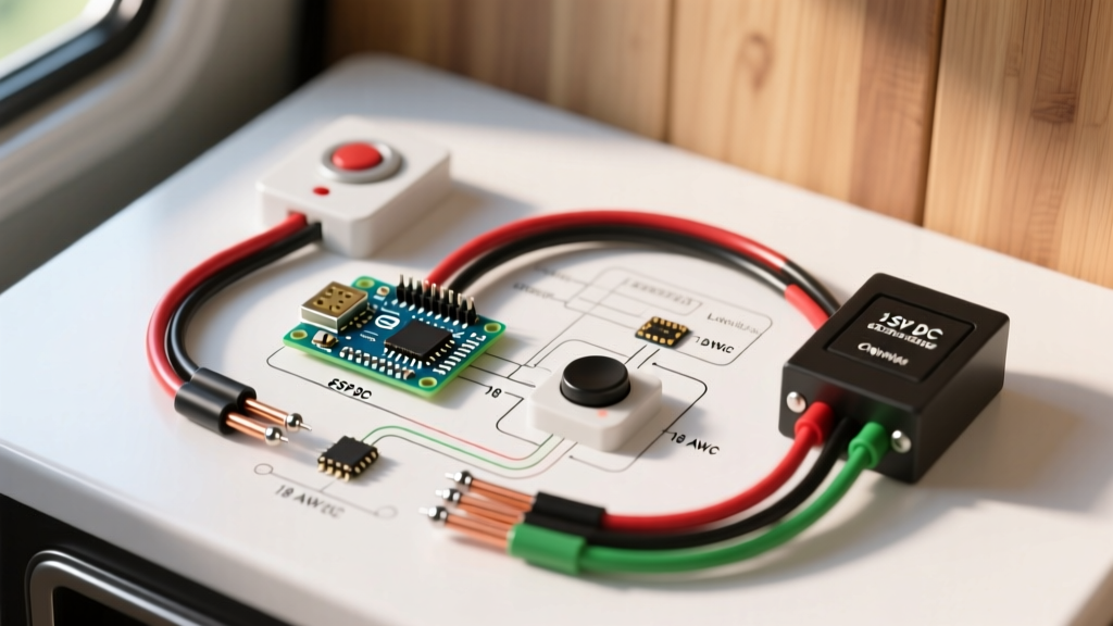
The following schematic outlines the exact current path from your DC distribution panel to the exterior button and interior chime.
Step 1: Power Tap and Fusing
Locate your 12V DC fuse panel (e.g., Blue Sea ST Blade). Insert a 2A fuse into an available slot connected to the positive bus bar. Attach an 18 AWG red wire to the fused load terminal using a fully insulated ring terminal. This is your primary positive feed.
Step 2: Routing to the Exterior Switch
Run the 18 AWG red wire from the fuse box to the exterior entry door. Critical Edge Case: If you are routing wire through the door hinge area, you must use a flexible rubber loom and a door-jamb grommet. Pinching the wire between the door frame and the chassis will cause a dead short, potentially melting the wire before the 2A fuse blows due to the high instantaneous current of a 12V battery bank.
Step 3: The Momentary Switch Connection
Connect the red positive feed to Terminal 1 of your IP67 momentary push button. The switch acts as a simple interrupter. When pressed, it completes the circuit. Connect a second length of 18 AWG red wire to Terminal 2 of the switch, and route this wire back into the interior ceiling or wall cavity where the chime will be mounted.
Step 4: Chime Integration
Connect the red wire coming from the switch to the Positive (+) terminal on the 12V DC chime. Next, attach an 18 AWG black wire to the Negative (-) terminal on the chime.
Step 5: Grounding to the Negative Bus Bar
Route the black negative wire back to your main DC negative bus bar. Never ground the chime directly to the vehicle's sheet metal chassis. Modern RVs and campervans often use composite panels, fiberglass, or painted steel that lacks a reliable ground path. Always return the circuit to the dedicated negative bus bar, which is bonded to the battery bank's negative terminal. This complies with NFPA 1192 Standard on Recreational Vehicles, which mandates dedicated negative return conductors for all 12V DC circuits.
Pro-Tip for 2026 Smart RV Builds: If your RV utilizes a Victron Energy Cerbo GX or similar central monitoring system, you can wire the momentary switch to a digital input on the Cerbo. This allows the system to trigger an interior relay for the chime while simultaneously sending a push notification to your smartphone when someone presses the doorbell, even if you are sitting outside by the campfire.
Advanced Scenario: Wiring a Smart AC Doorbell (Ring/Nest) in an RV
Many owners want the video capabilities of a Ring or Nest doorbell. These devices strictly require 16V-24V AC power. To achieve this, you cannot use a standard residential transformer, as they require 120V AC shore power and will not function while you are boondocking off-grid.
The Solution: You must install a 12V DC to 16V AC Isolated Inverter (often sold as a smart doorbell power supply for RVs).
- Tap a 5A fused 12V DC source from your main panel.
- Wire the 12V DC input to the inverter module.
- The inverter will output 16V AC via two low-voltage wires.
- Wire the 16V AC output directly to the smart doorbell's 'AC1' and 'AC2' terminals (polarity does not matter on AC).
- Ensure the inverter is mounted in a ventilated interior cabinet, as DC-to-AC conversion generates heat.
Voltage Drop Calculations and Wire Gauge Sizing
One of the most common failure modes in large Class A motorhomes is voltage drop. A doorbell button located at the rear entry door of a 40-foot motorhome might require a 60-foot total wire run (30 feet positive, 30 feet negative) from the front-mounted fuse panel.
Let us calculate the voltage drop for a 12V DC MP3 chime drawing 0.5 Amps over a 60-foot total run using 18 AWG copper wire:
- Resistance of 18 AWG Copper: ~6.38 Ohms per 1,000 feet.
- Total Resistance for 60 feet: 0.38 Ohms.
- Voltage Drop (V = I x R): 0.5A x 0.38 Ohms = 0.19 Volts.
A 0.19V drop on a 12V system is roughly 1.5%. The National Electrical Code (NEC) and ABYC standards recommend keeping voltage drop below 3% for critical electronics and below 10% for general appliances. Therefore, 18 AWG is perfectly adequate for standard 12V DC chimes, even in the longest motorhomes. However, if you are wiring a high-draw 12V DC solenoid-based horn or a smart doorbell inverter drawing 3+ Amps, you must step up to 14 AWG or 12 AWG wire to prevent the chime from sounding weak or the inverter from faulting out.
Troubleshooting Common RV Doorbell Failures
| Symptom | Probable Cause | Actionable Fix |
|---|---|---|
| Chime sounds weak or distorted | Voltage drop due to undersized wire or poor crimp connections. | Measure voltage at the chime terminals while the button is pressed. If below 11.5V, upgrade to 14 AWG wire and re-crimp all terminals. |
| Chime rings randomly ('Ghost Ringing') | Induced electromagnetic interference (EMI) from adjacent 120V AC wiring. | Ensure 18 AWG DC doorbell wires are routed at least 2 inches away from any 120V AC shore power or inverter cables. |
| Button is stuck / constantly ringing | Water ingress inside the exterior IP67 switch causing an internal short. | Replace the switch. Apply dielectric grease to the spade terminals before installing the new marine-grade button. |
| System works on shore power, but not on battery | The fuse is tapped to a 'Shore Power Only' accessory bus rather than the main 12V house bank. | Move the fuse tap to a constant 12V DC bus bar that is active regardless of the inverter/charger status. |
Final Safety and Code Compliance Checks
Before sealing up your interior panels, perform a continuity test with a multimeter to ensure no stray strands of copper are bridging the positive and negative terminals at the chime. Secure all wire runs with adhesive-backed cable mounts and zip ties every 12 to 18 inches to prevent the wires from rattling against the metal chassis during highway transit. By following this exact wiring diagram for doorbell systems, you ensure a robust, weatherproof, and electrically safe entry notification system tailored specifically for the rigorous demands of the RV lifestyle.