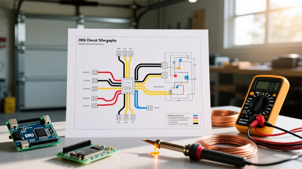

Decoding the Wiring Diagram for 2006 Chevy Silverado Radio Systems
The 2006 Chevrolet Silverado represents the final model year of the legendary GMT800 platform. While mechanically robust, its electrical architecture introduces specific challenges for aftermarket mobile electronics. Finding an accurate wiring diagram for 2006 Chevy Silverado radio replacement is only the first step; executing the install while maintaining safety, preserving the Class 2 serial data bus, and adhering to automotive electrical codes is where most DIYers fail. This guide focuses strictly on safety protocols, code-compliant splicing, and preventing catastrophic parasitic draws or SRS (airbag) faults.
The 2006 Silverado 24-Pin Harness: Base vs. Bose
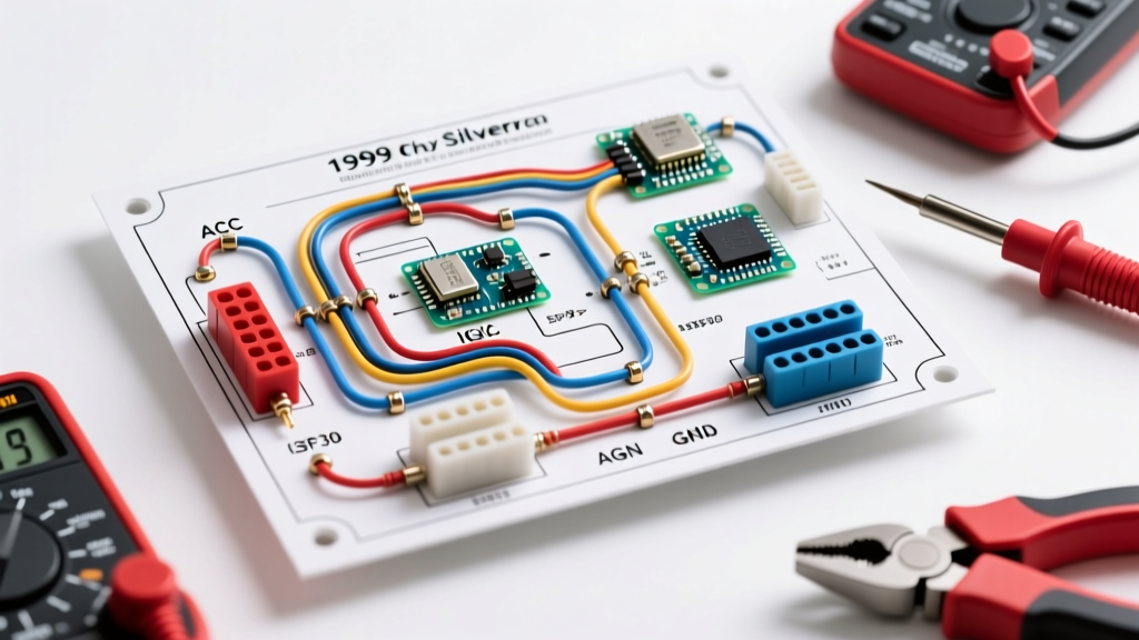
Before cutting a single wire, you must identify your factory audio tier. The 2006 Silverado utilizes a 24-pin primary connector, but the pinout and amplifier integration differ vastly between the Base and Bose systems. Below is the critical safety and power pinout reference.
| Wire Color | Function | Gauge | Safety & Compliance Notes |
|---|---|---|---|
| Orange | +12V Constant (Battery) | 18 AWG | Always verify with a multimeter. Do not rely solely on color. |
| Brown | +12V Accessory (Switched) | 18 AWG | In some GMT800 trims, this is dormant and relies on Class 2 Data. |
| Black/White | Chassis Ground | 18 AWG | Must be terminated to bare, unpainted metal. Max resistance: 0.05 ohms. |
| Yellow | Class 2 Serial Data | 22 AWG | CRITICAL: Never splice, tap, or ground this wire directly. |
The Class 2 Data Bus: Avoiding U-Codes and BCM Faults
The most dangerous wire in the 2006 Silverado radio harness is the Yellow Class 2 Serial Data line. General Motors uses this single-wire multiplex bus to allow the Body Control Module (BCM), radio, and instrument cluster to communicate.
Safety Warning: Using a 'vampire tap' or scotch-lock on the Yellow Class 2 wire can introduce resistance or capacitance that corrupts data packets. This can trigger U1000 or U1305 diagnostic trouble codes, potentially disabling your ABS or causing the BCM to stay awake, resulting in a dead battery within 24 hours.
To safely bypass the GM Theftlock (anti-theft) system and provide a proper +12V accessory signal to an aftermarket radio, you must use a data interface module. As of 2026, the industry standards are the PAC RP5-GM11 (approx. $85) or the Axxess GMOS-04 (approx. $110). These modules safely 'listen' to the Class 2 bus via a high-impedance T-tap connection without drawing enough current to corrupt the network topology.
IPC/WHMA-A-620 Compliant Splicing Techniques
Automotive environments subject wiring to extreme thermal cycling (-40°F to 185°F) and high-frequency vibration. The IPC/WHMA-A-620 standard for wiring harness assemblies explicitly dictates how wire splices should be executed to ensure mechanical and electrical integrity. Twist-and-tape methods are strictly non-compliant and pose a severe fire hazard.
Step-by-Step SolderSeal Protocol
- Strip and Stagger: Strip 3/16 inch of insulation. If splicing multiple wires (e.g., constant power and memory), stagger the cuts by 1 inch to prevent a single bulky node that can short against the dash frame.
- Use MIL-Spec SolderSeal: Slide a polyolefin heat shrink sleeve with pre-formulated solder rings and adhesive lining over the wire. (Cost: ~$15 for a 50-piece kit from 3M or WaterTite).
- Heat Application: Use a heat gun set to 350°F. Heat the center to melt the solder ring, then move to the edges to activate the waterproof adhesive. The adhesive must squeeze out slightly at both ends, creating a hermetic seal against copper oxidation.
- Pull Test: Per SAE International guidelines, a proper 18 AWG solder-seal splice should withstand a minimum pull force of 15 lbs without failure.
SRS Airbag Interference and Dash Safety
When removing the 2006 Silverado's dash bezel and radio brackets, you will be working in close proximity to the Supplemental Restraint System (SRS). The National Highway Traffic Safety Administration (NHTSA) strictly warns against probing or modifying SRS circuits.
- Identify Yellow Looms: Any wire encased in yellow tubing or featuring yellow connectors under the driver's side dash is part of the airbag circuit.
- Tool Safety: Never use metal pry tools near yellow SRS connectors. A short across the squib circuit can deploy the steering wheel airbag, causing severe injury and $1,200+ in replacement costs.
- Battery Disconnect: Always disconnect the negative battery terminal and wait a minimum of 15 minutes before beginning work to allow the SRS backup capacitors to discharge.
Proper Grounding and Fuse Tapping Protocols
Aftermarket radios and interface modules require dedicated, low-resistance grounds. Relying on the factory 18 AWG Black/White ground wire is often insufficient for modern high-wattage head units, leading to alternator whine and voltage sag.
Creating a Compliant Ground Point
Run a dedicated 12 AWG oxygen-free copper (OFC) ground wire from the radio chassis to a factory metal bolt under the dash. Use 80-grit sandpaper to remove all paint and primer from the contact patch. Apply a small dab of dielectric grease over the ring terminal after tightening to prevent galvanic corrosion, then verify continuity to the battery negative terminal using a digital multimeter (target: <0.05 ohms).
Fuse Tapping: Add-A-Circuit vs. Piercing
If your interface module requires an additional switched 12V source and the Brown wire is dormant, never pierce the HVAC or cigarette lighter wires. Instead, use an Add-A-Circuit (ATO/ATC) fuse tap at the Instrument Panel (I/P) fuse block.
Compliance Rule: Ensure the combined amperage of the original circuit and your new radio tap does not exceed 120% of the fuse block's rated wire capacity. Typically, tapping the 10A 'Radio' or 'Accessory' slot with a 5A secondary fuse is the safest, code-compliant route.
Troubleshooting Post-Install Parasitic Draws
The 2006 Silverado's BCM features a complex 'sleep' cycle. If the Class 2 data bus is kept awake by an improperly wired aftermarket radio, the vehicle will suffer a parasitic draw that kills the battery overnight.
The 20-Minute Sleep Test
- Reconnect the battery and roll up all windows.
- Turn off the ignition, remove the key, and ensure all dome lights are off.
- Wait exactly 20 minutes. The GMT800 BCM takes up to 20 minutes to fully power down its internal relays and enter sleep mode.
- Connect a multimeter set to the 10A DC setting in series with the negative battery terminal.
- Acceptable Draw: A healthy 2006 Silverado should read between 20mA and 50mA (0.02A - 0.05A).
- Failure Mode: If the draw remains above 200mA, your interface module is likely backfeeding the Class 2 bus or the accessory wire. Re-verify your PAC or Axxess module DIP switch settings and wiring pinouts.
By respecting the GMT800 electrical architecture, utilizing high-impedance data interfaces, and adhering to IPC-A-620 splicing standards, you ensure your 2006 Chevy Silverado radio upgrade is both functionally flawless and electrically safe for the long haul.