
Understanding the Anatomy of Compressor Pressure Switches
When upgrading, repairing, or building a custom stationary air compressor, interpreting the pressure switch for air compressor wiring diagram is the most critical step to prevent motor burnout, contact welding, and electrical fires. Modern single-phase compressors typically utilize diaphragm-style pressure switches, with the Schneider Electric Square D 9013FHG series and the Condor MDR-3 being the industry standards in 2026. A standard Square D 9013FHG12J20M1X costs between $28 and $42, while heavy-duty Condor models range from $65 to $95.
Before routing any wires, you must understand the internal terminal architecture. Unlike standard household switches, compressor pressure switches manage high inrush currents (Locked Rotor Amps, or LRA) and integrate pneumatic unloader valves.
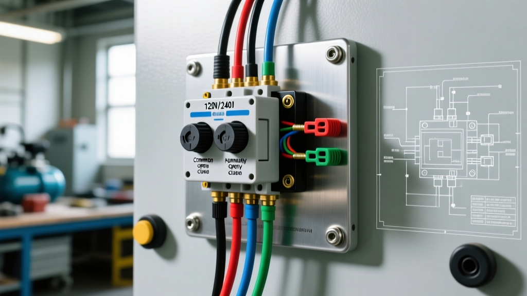
Key Terminal Identifications
- Line Terminals (L1, L2): The incoming power source from the branch circuit breaker. On 120V systems, L1 is Hot (Black) and L2 is Neutral (White). On 240V systems, both are Hot (Black and Red/White).
- Load Terminals (T1, T2): The outgoing power to the compressor motor. These must match the Line terminals phase-for-phase to maintain correct motor rotation (critical for 3-phase, but good practice for single-phase).
- Ground Lug (Green Screw): Connects to the metal chassis of the switch and the motor frame. This is non-negotiable for safety.
- Unloader Port (1/4" Brass Flare): Not an electrical terminal, but a pneumatic one. It connects to the check valve and bleeds trapped head pressure when the motor stops, allowing the motor to restart under no-load conditions.
Selecting Wire Gauge and Breaker Size
A common failure mode in DIY compressor builds is undersized wiring, which causes voltage drop. If the voltage at the motor drops below 10% of its rated nameplate voltage during startup, the contactor will chatter, generating excessive heat and welding the internal switch contacts.
| Motor HP | Voltage | Full Load Amps (FLA) | Min. Wire Gauge (Copper) | Breaker Size (Inverse Time) |
|---|---|---|---|---|
| 1.5 HP | 120V | 15A | 12 AWG | 20A |
| 2.0 HP | 240V | 10A | 14 AWG | 15A |
| 3.0 HP | 240V | 14A | 12 AWG | 20A |
| 5.0 HP | 240V | 22A | 10 AWG | 30A |
Note: For wire runs exceeding 50 feet, always upsize the wire gauge by one step to mitigate voltage drop.
Step-by-Step: Pressure Switch for Air Compressor Wiring Diagram Execution
Follow this precise workflow to terminate your wiring safely and reliably. You will need a Klein 11055 wire stripper, a calibrated torque screwdriver (Wiha or equivalent), and a Fluke 117 multimeter.
Phase 1: Preparation and Safety Lockout
- Lockout/Tagout (LOTO): Turn off the dedicated branch circuit breaker at the main panel. Apply a physical lockout hasp. Verify zero voltage at the conduit entry point using your multimeter (test Hot-to-Ground and Hot-to-Neutral).
- Conduit and Strain Relief: Feed your THHN wires or Romex through the 1/2" NPT knockout on the bottom of the switch housing. Secure the cable with a metallic strain relief connector. Never leave wires hanging loosely through the knockout, as vibration will sever the copper strands over time.
- Strip the Wires: Strip exactly 1/2 inch of insulation from 12-14 AWG wires. Stripping too little causes the screw to bite the insulation (high resistance); stripping too much exposes bare copper, creating a short-circuit hazard.
Phase 2: Terminating the Line and Load
- Line Side (Power In): Connect the incoming Hot wire(s) to the terminals marked LINE or L1/L2. If using 120V, connect the Hot to L1 and the Neutral to L2. If using 240V, connect Hot 1 to L1 and Hot 2 to L2.
- Load Side (Motor Out): Connect the motor leads to the terminals marked MOTOR or T1/T2. Ensure the wire routing does not cross over the moving diaphragm mechanism or the unloader valve pin.
- Torque Specifications: Tighten the terminal screws to 12 to 15 in-lbs. Under-torquing leads to arcing; over-torquing strips the brass threads or crushes stranded wire, reducing the contact surface area.
Phase 3: Grounding and Unloader Connection
- Grounding: Terminate the bare copper or green ground wire to the designated green grounding screw on the metal chassis. Bond the motor frame to the same ground loop.
- Pneumatic Unloader: Wrap the 1/4" brass flare nut with two layers of PTFE tape (or use liquid pipe sealant rated for compressed air). Thread it into the unloader port and tighten with a 7/16" wrench. Do not overtighten, as the brass pilot valve housing is prone to cracking.
Expert Warning: Never wire a compressor motor directly to a standard wall toggle switch or a lighting dimmer. Compressor motors require a switch with a specific Horsepower (HP) rating that can handle the inductive kickback and high LRA without arcing.
Wiring Matrix: Single-Phase 120V vs. 240V Configurations
The physical wiring diagram changes based on your supply voltage. Use this matrix to verify your connections before energizing the system.
| Terminal | 120V Single-Phase Setup | 240V Single-Phase Setup |
|---|---|---|
| L1 (Line) | Black (Hot - 120V) | Black (Hot Leg 1 - 240V) |
| L2 (Line) | White (Neutral) | Red or White-taped (Hot Leg 2 - 240V) |
| T1 (Load) | Motor Lead 1 (Hot) | Motor Lead 1 (Hot) |
| T2 (Load) | Motor Lead 2 (Neutral) | Motor Lead 2 (Hot) |
| Ground | Bare Copper / Green | Bare Copper / Green |
Calibrating Cut-In and Cut-Out Pressures
Once wired, you must calibrate the switch to match your tank's safety relief valve rating. Most standard shop compressors use a 100 PSI cut-in and 135 PSI cut-out. Under the switch cover, you will find two adjustment screws:
- Large Center Screw (Range Screw): Adjusts both cut-in and cut-out pressures simultaneously. Clockwise increases pressure.
- Smaller Offset Screw (Differential Screw): Adjusts the gap (differential) between cut-in and cut-out. Clockwise widens the gap.
Crucial Safety Rule: Your cut-out pressure must always be set at least 10 PSI below the pop-off rating of your tank's ASME-certified safety relief valve. If your relief valve is rated for 150 PSI, do not exceed a 135-140 PSI cut-out.
Advanced Troubleshooting: Edge Cases and Failure Modes
Even with a perfect wiring diagram execution, environmental and mechanical factors can cause system failures. Here is how to diagnose the most common edge cases.
1. Contact Welding and Motor Run-On
Symptom: The compressor reaches cut-out pressure, but the motor continues to run until the thermal overload trips or the relief valve blows.
Root Cause: The internal silver-cadmium contacts have welded together due to excessive arcing. This happens when the switch's HP rating is lower than the motor's actual HP, or when the switch has exceeded its 100,000-cycle mechanical lifespan.
Solution: Replace the switch immediately. Do not attempt to file or sand the contacts, as this removes the arc-resistant coating and creates a fire hazard.
2. Unloader Valve Continuous Bleed (Hissing)
Symptom: A continuous hissing sound from the pressure switch after the motor stops, lasting longer than 5 seconds.
Root Cause: The internal pilot valve pin is fouled with carbon buildup, or the unloader seat O-ring is degraded. It can also indicate a failed tank check valve allowing tank pressure to backfeed into the unloader tube.
Solution: First, isolate the tank check valve. If the hissing stops, replace the check valve ($15-$25). If the hissing continues, rebuild the switch unloader kit (typically a $4-$8 kit containing a new pin, spring, and Viton O-rings).
3. Switch Chattering (Rapid Cycling)
Symptom: The switch rapidly clicks on and off at the cut-in pressure, failing to engage the motor fully.
Root Cause: Severe voltage drop across the line. As the motor attempts to start, it pulls high LRA, dropping the voltage below the switch's holding threshold, causing it to open, which removes the load, restoring voltage, and closing it again.
Solution: Measure voltage at the L1/L2 terminals while the motor is attempting to start. If it drops below 108V (on a 120V system) or 216V (on a 240V system), you must upsize your branch circuit wiring or shorten the run length.
Code Compliance and Safety Standards
All compressor wiring must adhere to the National Electrical Code (NEC), specifically Article 430 (Motors, Motor Circuits, and Controllers). Section 430.83 mandates that the controller (pressure switch) must have a horsepower rating not less than the motor it controls. Using a 20-Amp lighting switch for a 3HP motor is a direct NEC violation and will void your equipment insurance.
Furthermore, the Occupational Safety and Health Administration (OSHA) requires proper grounding and LOTO procedures for all industrial and commercial compressed air systems. For deeper insights into system efficiency and pneumatic leak prevention, consult the U.S. Department of Energy's Compressed Air Systems guidelines, which detail how poorly maintained switches and leaky unloaders can increase facility energy costs by up to 20%.
By strictly following this pressure switch for air compressor wiring diagram tutorial, utilizing correctly gauged wire, and adhering to NEC torque and grounding specifications, you will ensure a safe, reliable, and long-lasting compressed air setup.