
Wiring an in-ground swimming pool is one of the most heavily regulated electrical projects a homeowner or contractor can undertake. Because water and electricity are a lethal combination, the National Electrical Code (NEC) Article 680 enforces strict guidelines for clearances, grounding, and equipotential bonding. Whether you are upgrading to a modern variable-speed pump or installing a new lighting system, understanding your pool electrical wiring diagram is critical for safety and passing local inspections.
This step-by-step walkthrough covers the complete wiring sequence for a standard in-ground residential pool, including the equipotential bonding grid, conduit runs, 240V pump motor connections, and 12V LED lighting circuits. All pricing and code references reflect the 2026 landscape, incorporating the latest NEC mandates for GFCI protection and variable-speed pump efficiency standards.
Essential Components & 2026 Material Costs
Before pulling any wire, you must gather code-compliant materials. Standard indoor NM-B (Romex) cable is strictly prohibited in wet locations and underground conduit. You must use THWN or THWN-2 copper conductors.
| Component | Specification / Model Example | 2026 Est. Cost |
|---|---|---|
| Bonding Wire | #8 AWG Bare Solid Copper | $1.15 / ft |
| Pump Circuit Wire | #10 AWG THWN-2 (Black, Red, White, Green) | $0.85 / ft |
| Conduit | 3/4" PVC Schedule 80 (Underground) | $2.40 / ft |
| GFCI Breaker (2-Pole) | Square D QO220GFI (20A, 240V) | $155.00 |
| Pool Light Transformer | Pentair IntelliBrite 12V, 300W | $285.00 |
| Junction Box | Intermatic PA114T (Pool/Spa Listed) | $65.00 |
Step 1: Planning the Equipotential Bonding Grid
The most frequently failed inspection point in pool wiring is the equipotential bonding grid. Bonding does not carry current under normal conditions; instead, it equalizes the voltage gradient between all conductive surfaces around the pool to prevent shock hazards.
Bonding Requirements for Concrete vs. Vinyl Pools
- Concrete Pools: The structural reinforcing steel (rebar) must be bonded together using #8 AWG solid copper wire and listed bronze grounding clamps. If the rebar is encapsulated in a non-conductive membrane, you must install an alternate copper mesh grid in the soil.
- Vinyl/Fiberglass Pools: You must install a copper mesh grid or a continuous #8 AWG bare copper loop buried 4 to 6 inches deep in the earth, extending 3 feet horizontally from the pool wall.
Inspector Pro-Tip: Every metallic component within 5 feet of the pool edge—including ladders, diving stands, metal coping, and the pool pump motor housing—must be tied into this #8 AWG bonding loop. Use direct-burial rated, tin-plated bronze lugs (like the King Innovation 822TB) to prevent galvanic corrosion.
Step 2: Running Conduit and Pulling THWN Wire
Once the bonding grid is verified, you will run the branch circuits from the main electrical panel to the pool equipment pad. According to the National Fire Protection Association (NFPA 70), underground wiring must be installed in rigid metal conduit, intermediate metal conduit, or PVC Schedule 80.
- Trenching: Dig a trench 18 to 24 inches deep from the panel to the equipment pad.
- Conduit Assembly: Use 3/4-inch PVC Schedule 80 for underground runs. Glue all joints with PVC primer and cement to ensure a watertight seal. Install a pull box every 100 feet or if the conduit has more than four 90-degree bends.
- Pulling Wire: Use a fiberglass fish tape. For a 240V pump circuit, pull four #10 AWG THWN-2 wires: Black (Line 1), Red (Line 2), White (Neutral, required for 120V control circuits in modern VFD pumps), and Green (Equipment Grounding Conductor).
Step 3: Wiring the Pool Pump Motor (240V VFD Setup)
Modern pool codes and the U.S. Department of Energy efficiency mandates heavily favor Variable Frequency Drive (VFD) pumps, such as the Pentair IntelliFlo3 or Hayward EcoStar. These pumps require a 240V dedicated circuit.
Pump Terminal Connections
Open the pump's wiring compartment. You will typically find a terminal block labeled L1, L2, and Ground.
- Connect the Black wire to L1.
- Connect the Red wire to L2.
- Connect the White wire to the designated neutral terminal (crucial for the pump's internal digital display and Wi-Fi module).
- Connect the Green wire to the green grounding screw on the motor housing.
- Attach the #8 AWG bonding wire to the external brass bonding lug on the outside of the pump motor.
Torque Specification: Always use a calibrated torque screwdriver. Most pump manufacturers specify 35 in-lbs for terminal connections. Loose connections on a VFD pump will cause voltage drops, leading to nuisance GFCI tripping and premature motor failure.
Step 4: Pool Light Wiring and Junction Box Placement
Pool lighting requires a separate circuit and strict adherence to wet-niche or dry-niche fixture rules. Most modern installations use 12V LED fixtures (like the Pentair IntelliBrite) to minimize shock risk, which requires a step-down transformer.
Junction Box and Transformer Siting
The pool light junction box and the 12V transformer must be located at least 4 feet horizontally from the inside wall of the pool. Furthermore, the junction box must be elevated at least 8 inches above the maximum water level and 4 inches above grade to prevent water ingress.
- Run a 120V circuit (#12 AWG THWN) from a GFCI-protected breaker to the pool light junction box.
- Inside the junction box, connect the 120V wires to the primary side of the 12V transformer.
- Run the low-voltage 12V wires from the transformer's secondary side to the wet-niche light fixture.
- Ensure the light fixture's cord is coiled inside the wet niche housing to allow for future bulb/lens servicing without needing to pull new wire through the conduit.
Step 5: Main Panel and GFCI Breaker Integration
The NEC mandates GFCI protection for all 15A and 20A, 125V receptacles within 20 feet of the pool, as well as for the pool pump motor circuit. For a 240V pump, you must use a 2-pole GFCI breaker (e.g., Square D QO220GFI or Siemens Q220GFI).
Wiring the 2-Pole GFCI Breaker
- Snap the breaker into the panel bus bars.
- Connect the White neutral pigtail from the breaker directly to the panel's neutral bar. (Do not skip this; the GFCI electronics require 120V to operate the internal test circuit).
- Connect the circuit's Black and Red wires to the breaker's LOAD terminals.
- Connect the circuit's White wire to the breaker's coiled neutral pigtail (if the breaker features a load-neutral terminal) or directly to the neutral bar, depending on the specific breaker manufacturer's diagram.
- Land the Green equipment grounding wire on the panel's ground bus bar.
Common Failure Modes & Troubleshooting
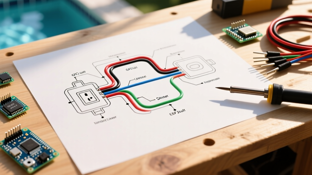
Even with a perfect pool electrical wiring diagram on paper, field conditions can introduce faults. Here are the most common issues encountered during the first season of operation:
1. Nuisance GFCI Tripping on the Pump Circuit
Cause: VFD pumps generate high-frequency harmonics and minor leakage currents during startup. If the wire run exceeds 100 feet without being upsized, voltage drop can cause the GFCI's internal microprocessor to misinterpret the phase shift as a ground fault.
Fix: Upsize the THWN conductors from #10 to #8 AWG for runs over 75 feet. Ensure the equipment ground is continuous and unspliced.
2. Corrosion on the Bonding Lug
Cause: Using standard steel or aluminum lugs in a chlorine-rich environment leads to rapid galvanic corrosion, breaking the equipotential bond.
Fix: Replace with tin-plated bronze lugs and apply a layer of antioxidant compound (like Noalox) over the connection, then wrap it in a self-fusing silicone rescue tape for a watertight seal.
3. Pool Light Flickering or Failing Prematurely
Cause: Voltage drop on the 12V low-voltage side. 12V LED lights are highly sensitive to voltage drops; a drop below 10.5V will cause flickering and shorten the LED driver's lifespan.
Fix: Use #10 AWG wire for the 12V run from the transformer to the light if the distance exceeds 30 feet. Never use #12 or #14 AWG for long 12V pool light runs.
Final Safety and Inspection Checklist
Before filling the pool or turning on the breakers, verify your work against the U.S. Consumer Product Safety Commission (CPSC) pool safety guidelines. Test all GFCI breakers using the physical "Test" button on the breaker face—do not rely solely on plug-in testers. Ensure all conduit bodies are sealed with duct seal putty to prevent water from migrating back into the main electrical panel. Finally, have your local Authority Having Jurisdiction (AHJ) inspect the bonding grid before you backfill the trench or pour the concrete equipment pad.