
Why GM Wiring Diagrams Seem Like a Foreign Language (and How to Fix It)
If you have ever stared at a factory General Motors service manual schematic and felt completely overwhelmed, you are not alone. GM wiring diagrams are notoriously dense, packed with proprietary abbreviations, complex CAN bus networks, and circuit numbers that look like random lottery picks. However, whether you are planning a classic C10 restomod, executing an LS/LT engine swap, or simply repairing a faulty window motor on a 2015 Silverado, understanding these diagrams is non-negotiable. This installation planning guide breaks down GM wiring diagrams for dummies, transforming intimidating schematics into a clear, actionable roadmap for your next electrical project.
The Anatomy of a GM Schematic
Before you can plan an installation, you must understand the visual language GM uses. Unlike generic automotive diagrams, GM relies on a strict alphanumeric coding system. Every wire is identified by a Circuit Number (e.g., Circuit 440 for fuel pump relay control, or Circuit 1046 for the starter signal). Next to the circuit number, you will see the Wire Color and Wire Gauge. GM uses specific abbreviations for colors: ORN (Orange), PNK (Pink), DK BLU (Dark Blue), and LT GRN (Light Green). A wire labeled 14 DK BLU is a 14-AWG Dark Blue wire. Furthermore, GM identifies grounds with a 'G' prefix (e.g., G101 for the front engine block ground, G200 for the cabin ground) and connectors with a 'C' prefix (e.g., C101 for the main engine-to-body bulkhead connector).
Step-by-Step Installation Planning for Beginners
Planning a GM wiring installation requires more than just buying a spool of wire and some crimpers. A structured approach prevents voltage drops, melted harnesses, and ECU communication failures.
- Map the ECM/BCM Requirements: Modern GM ECMs (like the E38, E67, or newer E92 controllers) require clean, stable power. Identify the main battery feed (usually heavy-gauge Orange or Red wires), the ignition-switched feeds (Pink), and the dedicated sensor grounds. Never share a sensor ground with a high-current accessory.
- Calculate Amperage and Voltage Drop: Use the diagram to identify the maximum current draw for each circuit. A standard GM fuel pump might pull 12-15 amps, but high-performance aftermarket pumps (like a Walbro 450 or Aeromotive 340) can pull 20+ amps, requiring an upgrade from the factory 14-AWG to 10-AWG wire.
- Plan the Routing and Bulkhead Pass-Throughs: Determine where the harness will cross the firewall. GM factory diagrams show the exact grommets used. If you are doing a custom swap, plan to use a sealed firewall bulkhead connector (like a 12-cavity Weather-Pack or a Deutsch DT) rather than just poking wires through a rubber grommet, which leads to chafing and shorts.
Pro-Tip on GM Color Codes: In almost all GM schematics, Pink (PNK) is reserved for ignition-switched 12V power (Run/Start), while Orange (ORN) or Red (RED) is constant 12V battery power. Black (BLK) or Black/White (BLK/WHT) is universally used for chassis and component grounds. Sticking to these color standards makes future troubleshooting infinitely easier.
Essential Wire Gauge Matrix for GM Swaps and Repairs
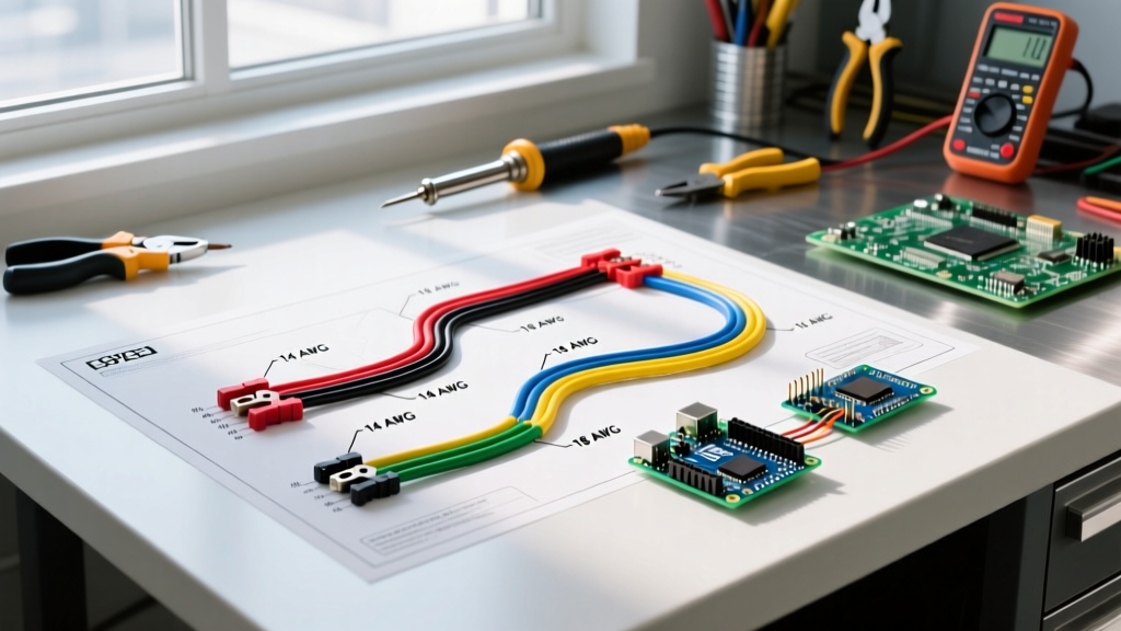
Using the correct wire gauge is critical. Undersized wires cause voltage drops that can make GM electronic throttle bodies (ETB) throw P0121 or P2135 codes due to low reference voltage. Below is a practical planning matrix for common GM installation scenarios.
| Circuit Type | Typical Amperage | Recommended Wire Gauge | GM Factory Color Standard | Notes / Edge Cases |
|---|---|---|---|---|
| ECM Main Battery Feed | 25A - 40A | 8 AWG or 10 AWG | Orange / Red | Use 8 AWG if the battery is relocated to the trunk to minimize voltage drop. |
| Ignition Switched (Run/Start) | 5A - 15A | 12 AWG or 14 AWG | Pink | Feeds the ECM ignition relays and instrument cluster. |
| Fuel Pump Power | 12A - 22A | 10 AWG (12 AWG min) | Grey (GRY) | Upgrade to 10 AWG for high-flow EFI pumps; factory 14 AWG will overheat. |
| Injector Feeds | 2A - 4A per bank | 14 AWG or 16 AWG | Pink / Black | Modern GM ECUs use saturated or peak-and-hold drivers; 14 AWG is safe for all. |
| Starter Signal (Ckt 1046) | 1A - 2A | 16 AWG or 18 AWG | Purple (PPL) or Yellow | Low current; this triggers the starter relay, not the main solenoid directly. |
| Chassis / Block Grounds | 100A+ | 4 AWG or 2 AWG | Black | Crucial for LT/LS swaps. Add a dedicated 2 AWG strap from the engine block to the frame. |
Selecting the Right Connectors: Weather-Pack vs. Metri-Pack
A common mistake beginners make is buying the wrong GM-style connectors. GM transitioned from Weather-Pack to Metri-Pack in the early 1990s, and both are still used today depending on the application.
- Weather-Pack (150, 280, 560, 800 Series): These are the older, bulkier connectors with round pins and silicone rubber seals. They are excellent for high-current, harsh-environment applications like headlights, fuel pumps, and alternator feeds. The '150' series handles up to 20 amps, while the '280' handles up to 30 amps.
- Metri-Pack (150, 280, 630, 800 Series): Introduced to save space and improve reliability, Metri-Pack connectors feature flat, blade-style terminals. The Metri-Pack 280 is the undisputed king of GM engine sensors (MAF, MAP, TPS, O2 sensors) and ECM pins. If you are building a custom harness for an LS or LT engine, 90% of your sensor connections will use Metri-Pack 280 terminals.
Cost Analysis: Buying pre-made GM dealer pigtails can cost $30 to $75 per connector. By investing in a high-quality ratcheting crimper (like the Titan 12094430 equivalent or an IWISS Metri-Pack die set, roughly $45) and buying bulk Aptiv/Delphi terminals and seals ($0.15 to $0.25 each), you can build a superior, custom-length harness for a fraction of the cost.
Modern Integration: GMLAN and CAN Bus Planning
If your installation involves a 2006-or-newer GM vehicle, you will encounter GMLAN (General Motors Local Area Network). Unlike older analog wires, GMLAN uses a twisted-pair digital network (CAN High and CAN Low) to allow modules to talk to each other. When planning a swap or repair involving GMLAN, you must adhere to strict rules:
- Twisted Pair: The CAN High and CAN Low wires must be twisted together (typically 1 twist per inch) to reject electromagnetic interference (EMI) from the alternator and ignition coils.
- Termination Resistors: A GMLAN bus requires exactly two 120-ohm termination resistors—one at each end of the network. If you remove the BCM or Instrument Cluster during a race car conversion, you must install a physical 120-ohm resistor across the CAN High and CAN Low pins, or the ECM will throw U-codes (communication errors) and may default to limp mode.
- Splicing is Forbidden: Never use T-taps or butt-splices on a GMLAN bus. Any repair must be done by cutting out the damaged section and soldering in a new twisted-pair segment, or using a factory-approved splice clip.
Common GM Wiring Failure Modes (and How to Avoid Them)
Even with the best planning, specific GM architectures are prone to unique failure modes. Anticipate these during your installation:
- The 'Bad Ground' Cascade: GM engines (especially the LS1/LS2 and early EcoTec) rely heavily on the cylinder heads and intake manifolds for sensor grounding. If the engine block isn't grounded to the chassis, or if the head-to-block ground strap is missing, sensors will read erratic voltages. Fix: Always install a dedicated 4-AWG ground strap from the passenger side cylinder head to the chassis, and clean the mounting surface to bare metal.
- Ignition Switch Voltage Drop: Older GM vehicles (like the GMT800 Silverados) route high current through the ignition switch to power the PCM and fuel pump relays. Over time, the switch contacts burn, dropping the voltage below 10.5V, causing stalling or no-starts. Fix: Install a heavy-duty headlight/PCM relay upgrade kit (approx. $35) so the ignition switch only triggers a low-amp relay coil.
- Chafing at the Valve Cover: On LS and LT engines, the main harness often rests against the sharp edge of the valve cover or exhaust manifold. Fix: Use high-temp fiberglass braided sleeving (approx. $15 for 10 feet) and secure the harness with stainless steel Adel clamps, keeping it at least 2 inches away from exhaust components.
Recommended Authoritative Resources for GM Schematics
To plan accurately, you need the correct diagrams. Do not rely on blurry forum screenshots. Use these authoritative sources:
- Helm Incorporated: As the official publisher of GM Factory Service Manuals, Helm provides the exact wiring diagrams used by dealership technicians. Purchasing the specific year/model manual (typically $150-$250) is the best investment for complex BCM/ECM diagnostics.
- GM Upfitter (Body Builder Guides): If you are working on a GM truck or van (Express, Silverado, Colorado), the GM Body Builder Manuals are free and provide incredible detail on blunt-cut wires, auxiliary upfitter switches, and heavy-duty power distribution blocks.
- Aftermarket Harness References: Companies like Painless Performance offer detailed installation manuals and color-coded GM swap harnesses (ranging from $400 to $800) that simplify the factory diagram into a beginner-friendly format, ideal for standalone LS swaps.
FAQ: GM Wiring Diagrams for Dummies
What does a solid black dot mean on a GM wiring diagram?
A solid black dot indicates a physical splice or junction where two or more wires are permanently connected together inside the harness. If there is no dot, the wires merely cross over each other without making electrical contact.
Can I use standard copper wire for my GM engine swap?
Standard hardware store THHN copper wire is not rated for automotive use. It lacks the chemical resistance to oil, fuel, and extreme heat. Always use automotive-grade primary wire that meets SAE J1128 or TXL/GXL cross-linked polyethylene (XLPE) standards, which can withstand under-hood temperatures up to 125°C (257°F).
How do I find the exact pinout for my GM ECM connector?
GM diagrams label ECM connectors with a 'C' number (e.g., C1, C2, C3 for the E38 ECM). The schematic will show a grid view of the connector face. Pin 1 is always identified by a small triangle or a distinct cavity shape. Always verify the pinout against the specific RPO code and year of your ECM, as GM frequently changes pinouts between model years even if the physical connector looks identical.