
Mastering the 7 Pin Wiring Diagram for Trailer Electrical Systems
Towing a travel trailer, horse trailer, or heavy utility rig requires far more than a basic 4-pin flat connector. When you need to power electric brakes, interior 12V appliances, and reverse lights, the 7-pin RV blade connector is mandatory. Governed by the SAE J286 standard, this connector acts as the central nervous system between your tow vehicle and your trailer. In this tutorial, we treat your trailer’s electrical system as a remote appliance panel, breaking down the exact 7 pin wiring diagram for trailer installations, wire gauge mathematics, and load-management strategies for modern towing setups.
The Standard 7-Pin RV Blade Pinout Matrix
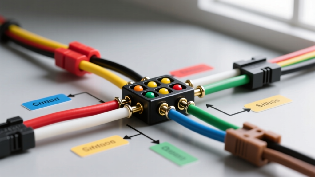
Before cutting any wires, you must understand the physical layout and color coding of the 7-way RV blade connector. A common pitfall for DIYers is assuming the 7-pin colors perfectly match the 4-pin flat colors (they do not; the left turn signal changes from Yellow to Red). Below is the definitive pinout matrix for the vehicle-side socket and trailer-side plug.
| Pin Position | Function | Standard Wire Color | Minimum Wire Gauge |
|---|---|---|---|
| Pin 1 (Top Center) | Ground (Chassis) | White | 10 AWG |
| Pin 2 (Top Right) | Left Turn / Stop | Red | 16 AWG |
| Pin 3 (Bottom Right) | Right Turn / Stop | Green | 16 AWG |
| Pin 4 (Center) | Tail / Running Lights | Brown | 16 AWG |
| Pin 5 (Bottom Left) | Electric Brakes | Blue | 10 AWG |
| Pin 6 (Top Left) | 12V Auxiliary Power | Black | 10 AWG (or 8 AWG) |
| Pin 7 (Bottom Center) | Reverse Lights / Aux | Yellow | 16 AWG |
Treating the Trailer as a Remote Appliance Panel
When wiring a trailer, it is highly beneficial to view the 7-pin connector not just as a lighting harness, but as a power distribution bus for remote appliances. Two specific pins handle heavy electrical loads that require precise engineering to prevent voltage drop and thermal failures.
The 12V Auxiliary Circuit (Pin 6) and Appliance Integration
Pin 6 (Black wire) provides a continuous 12V feed from the tow vehicle’s alternator to the trailer. This circuit is typically fused at 30A or 40A at the vehicle's distribution box. Modern campers use this pin to power 12V compressor refrigerators (like the Dometic CFX3 series), interior LED lighting, and 12V water pumps.
The Voltage Drop Problem: A standard 25-foot trailer harness using 10 AWG wire has a resistance of roughly 0.001 ohms per foot. If your 12V fridge draws 6A, the total round-trip voltage drop (50 feet of wire) is approximately 0.3V. However, if you daisy-chain additional appliances or use undersized 12 AWG wire, the voltage at the trailer's distribution panel can drop below 11.2V. At this threshold, sensitive appliance control boards will trigger low-voltage shutoffs, and compressor motors will stall and overheat. For trailers exceeding 25 feet, upgrading the Pin 6 Black wire to 8 AWG is a critical best practice.
Electric Brake Magnets (Pin 5) as Inductive Loads
Pin 5 (Blue wire) powers the electric brake magnets on the trailer axles. Unlike incandescent lights, brake magnets are highly inductive loads. A typical 10-inch or 12-inch electric brake assembly draws between 3.0A and 3.5A per wheel. On a dual-axle trailer, the Blue wire must safely carry up to 14A continuously during maximum braking events. Furthermore, when the brake controller (such as the Tekonsha Prodigy P3) pulses the current via PWM (Pulse Width Modulation), it generates inductive kickback. Using high-quality, stranded, pure-copper 10 AWG wire with abrasion-resistant cross-linked polyethylene (XLPE) insulation is mandatory to prevent shorting against the steel trailer frame.
Step-by-Step Wiring Tutorial
Step 1: Establishing a True Chassis Ground
The White wire (Pin 1) is the most critical connection in the entire 7 pin wiring diagram for trailer setups. Do not simply bolt the ground ring terminal to the exterior aluminum skin or a painted bumper. You must bond the ground wire directly to the bare steel trailer frame. Use a 3/8-inch bolt, a star washer to bite through any surface rust, and apply a coating of dielectric grease over the terminal after tightening to prevent galvanic corrosion.
Step 2: Routing and Securing the Harness
Use a molded 7-way harness (such as the Curt 58150 or Hopkins 48170) which features a built-in junction box. Route the harness along the interior of the trailer frame rails, securing it every 18 inches with UV-resistant nylon cable ties. Keep the wiring at least 4 inches away from exhaust components and moving suspension parts.
Step 3: Integrating the Brake Controller
The Blue wire runs from Pin 5 directly to the trailer's brake assemblies. On the tow vehicle side, this wire must connect to the output terminal of your electronic brake controller. Ensure the brake controller is mounted within easy reach of the driver and is perfectly level, as proportional controllers use internal accelerometers to calculate braking force.
Pro-Tip: Never splice the Blue brake wire using standard twist-on wire nuts or cheap crimp connectors. The vibration of towing will cause these to fail. Always use adhesive-lined marine-grade heat shrink butt connectors (rated for 12-10 AWG) and apply heat until the adhesive sealant bleeds out of both ends.
Essential Tools and 2026 Material Costs
To execute a professional-grade trailer wiring job, you need the right tools. Below is a realistic breakdown of materials and costs for a complete 7-pin rewiring project in 2026.
- Molded 7-Way Harness (8 ft): Curt 58150 or equivalent ($22 - $28)
- Trailer Wiring Junction Box: Spectro 7-Way Box ($15 - $18)
- Adhesive-Lined Heat Shrink (12-10 AWG): TICONN 120-piece kit ($14)
- Wire Strippers/Crimpers: Knipex MultiCrimp or Channellock 909 ($45 - $65)
- Digital Multimeter: Klein Tools MM400 or Fluke 115 ($40 - $180)
- Dielectric Grease: Permatex 22058 ($6)
- Pure Copper 10 AWG Wire (50 ft spool): ($35 - $45)
Total estimated cost for a premium, long-lasting harness replacement: $175 - $350, depending on tool ownership.
Advanced Troubleshooting: Failure Modes and Edge Cases
Even with a perfect 7 pin wiring diagram for trailer execution, environmental factors and component degradation can cause faults. Here is how to diagnose the most complex edge cases using a multimeter.
1. The 'Ground Loop' Backfeed
Symptom: When you press the brake pedal, the trailer's running lights dim, and the turn signals flash erratically. Diagnosis: The White ground wire has high resistance (corrosion or loose bolt). The electrical current is seeking an alternative path to ground, backfeeding through the Brown (tail light) circuit. Fix: Disconnect the trailer from the truck. Set your multimeter to the Ohms (Ω) setting. Measure resistance between the White wire pin on the trailer plug and the bare steel frame. It should read less than 0.5 ohms. If it reads higher, clean the ground point or run a secondary 10 AWG ground wire directly to the trailer's main appliance distribution panel.
2. Brake Controller 'SH' or 'OL' Error Codes
Symptom: Your Tekonsha or Curt brake controller displays 'SH' (Short) or 'OL' (Overload) when the trailer is connected. Diagnosis: A 'SH' code means the Blue brake wire is touching the trailer frame somewhere between the plug and the axles, or a brake magnet internal coil has shorted. An 'OL' code means the controller is detecting more than 15 amps of draw, usually indicating a seized brake magnet or a wiring short at the wheel hub. Fix: Disconnect the Blue wire at the junction box. Test continuity between the Blue wire and the White ground wire. If the multimeter beeps (continuity), you have a chafed wire under the trailer. Inspect the areas where the wiring passes through the axle hangers.
3. 12V Auxiliary Pin Voltage Sag
Symptom: The trailer's 12V water pump surges, or the interior lights flicker when the tow vehicle is idling. Diagnosis: The tow vehicle's alternator output drops at idle, and the 10 AWG Black wire is experiencing excessive voltage drop under load. Fix: Measure voltage at the vehicle's socket Pin 6, then measure at the trailer's distribution block with the water pump running. If the drop exceeds 0.8V, you must upgrade the Black wire to 8 AWG or install a DC-to-DC battery charger (like the Victron Orion-Tr Smart) in the trailer to regulate the voltage for sensitive appliances.
Authoritative References and Further Reading
For deeper technical specifications and safety standards regarding trailer towing and electrical systems, consult the following authoritative resources:
- eTrailer's Comprehensive Trailer Wiring FAQ - An industry-standard database for vehicle-specific wiring harnesses, pinout diagrams, and troubleshooting flows.
- Tekonsha Electronic Brake Controller Manuals - Official documentation for proportional brake controllers, including detailed PWM signaling and error code matrices.
- National Highway Traffic Safety Administration (NHTSA) - Federal guidelines on vehicle safety, towing capacities, and lighting requirements for commercial and recreational trailers.
By treating your trailer's 7-pin connector as a robust power distribution system rather than a simple lighting accessory, you ensure safe towing, protect expensive 12V appliances, and eliminate the frustrating electrical gremlins that plague amateur wiring jobs.