
Decoding the Craftsman Riding Mower Electrical Architecture
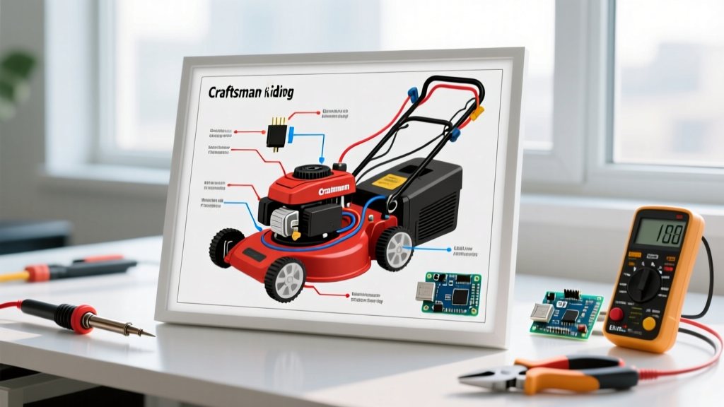
When you first look at a wiring diagram for a Craftsman riding mower, the web of colored lines and geometric symbols can feel overwhelming. Whether you are working on a classic Craftsman LT1500 with a Briggs & Stratton engine or a newer T225 series powered by a Kohler 19HP V-Twin, the underlying 12-volt DC electrical architecture follows a highly standardized logic. Understanding this logic is the difference between blindly swapping out $100 parts and accurately diagnosing a $2 microswitch failure.
As a motor wiring tutorial, this guide bypasses the fluff and dives directly into the exact wire gauges, pinouts, voltage specifications, and failure modes you need to trace circuits effectively in 2026. We will break the schematic down into four distinct subsystems: the high-amperage starter circuit, the ignition switch matrix, the safety interlock logic, and the stator charging system.
The 12-Volt Starter Circuit: Battery to Solenoid to Motor
The starter circuit is responsible for the highest current draw on the mower. A standard 14HP to 24HP Craftsman riding mower utilizes a 12V, 35Ah U1 group size battery capable of delivering 230 to 350 Cold Cranking Amps (CCA).
- Main Power Feed: A heavy-duty 10 AWG red cable runs directly from the positive battery terminal to the 'B' (Battery) post on the starter solenoid. This cable carries the full cranking load.
- Solenoid to Starter: Another 10 AWG red cable connects the 'S' (Starter) post on the solenoid directly to the starter motor's copper contact terminal.
- Trigger Circuit: A lighter 14 AWG wire (often red with a white trace, or solid purple) runs from the ignition switch, through the safety interlock relays, to the solenoid's small trigger spade. When this wire receives 12V, it energizes the solenoid coil, bridging the heavy contacts.
Pro Diagnostic Tip: If your mower clicks but won't crank, do not immediately replace the starter. Use a multimeter to measure the voltage drop across the solenoid's two large posts while holding the key in the 'START' position. A healthy solenoid will show a voltage drop of less than 0.2V. If you read 10V+ across the posts, the internal copper contacts are pitted and the $25 solenoid must be replaced, not the $95 starter motor.
The 6-Pin Ignition Switch Pinout Matrix
The ignition switch is the central nervous system of the mower's wiring diagram. Most Craftsman models use a universal 5-to-6 pin rotary switch. Miswiring this switch during a replacement is the leading cause of stator burnout and no-start conditions. Below is the standard pinout matrix for a magneto-ignition Craftsman mower.
| Terminal Letter | Wire Color (Typical) | Function | Voltage State (Run) |
|---|---|---|---|
| B | Red (10 AWG) | Battery Positive (Main Power In) | 12.6V Constant |
| S | Purple / Red-White | Solenoid Trigger (Start Only) | 12V (Crank Only) |
| M | Black / Gray | Magneto Kill (Grounds Ignition Coil) | Open (Floats in Run) |
| G | Black | Ground (Chassis Return) | 0V (Ground) |
| L | Blue / Yellow | Headlights / Accessories | 12V (When Switched On) |
| A1 / A2 | White / Green | PTO Clutch / Fuel Solenoid Power | 12V (Run/PTO Engaged) |
Note: The 'M' terminal must NEVER be connected to a 12V positive source. It is designed to ground the ignition coil's primary winding to stop the spark. Applying 12V to the 'M' terminal will instantly fry the ignition coil and potentially damage the wiring harness.
Safety Interlock Logic: Why Your Mower Won't Crank
Modern Craftsman mowers are governed by a series-circuit safety interlock system designed to prevent the engine from cranking in gear or starting with the mower deck engaged. When tracing a wiring diagram for a Craftsman riding mower, the interlock loop is usually the culprit for 'dead' electrical systems.
The Crank Interlock Path
- Brake Pedal Switch: The circuit begins at the ignition switch 'S' terminal, routing to the brake pedal switch. The brake must be fully depressed to close this Normally Open (NO) switch.
- PTO (Power Take-Off) Switch: From the brake switch, the wire routes to the PTO engagement switch. For the starter to engage, the PTO must be in the 'OFF' (disengaged) position.
- Transmission / Gear Selector: On manual gear-drive models, the shifter must be in neutral. On hydrostatic models (like the T225), this is bypassed if the brake is locked, but some models include a seat switch bypass relay.
- Starter Solenoid Trigger: Once all conditions are met, the 12V signal reaches the solenoid's small trigger spade.
According to the Briggs & Stratton Support Center, over 60% of small engine no-crank complaints are traced back to corroded spade connectors on the brake and PTO microswitches, rather than failed switches themselves. Always clean the terminals with electrical contact cleaner before replacing the $8 switches.
Stator and Regulator/Rectifier: The Charging System
Unlike a car, a riding mower does not use a belt-driven alternator. Instead, it uses a stator (a ring of copper coils mounted under the engine flywheel) and a solid-state Regulator/Rectifier (R/R). For deeper engine-specific schematics, the Kohler Engines Service Manuals provide excellent flywheel stator diagrams.
- The Stator Output: As the flywheel's magnets spin over the stator, it generates Alternating Current (AC). At 3600 RPM (full throttle), a healthy stator should output between 28V and 35V AC across its two yellow wires.
- The Regulator/Rectifier: The AC voltage enters the R/R (typically a finned aluminum block mounted to the engine shroud for cooling). The R/R converts the AC to DC and regulates it down to a safe 13.8V to 14.4V DC to charge the battery and run the headlights.
Failure Mode: If the R/R fails in an 'open' state, the battery will slowly drain while mowing, eventually killing the engine when the electric PTO clutch starves for voltage. If it fails 'closed', it will push 18V+ into the system, boiling the battery acid and blowing the headlights. Always test the R/R center output wire (usually white or red) with the engine at full throttle; if it reads above 14.8V DC, replace the regulator immediately.
Diagnostic Troubleshooting Matrix
Use this matrix to rapidly isolate electrical faults without relying on guesswork.
| Symptom | Probable Cause | Multimeter Test & Action |
|---|---|---|
| Engine cranks but won't start | Ignition coil grounded by faulty switch | Disconnect 'M' wire from ignition switch. If spark returns, replace the ignition switch ($20-$35). |
| Clicking sound, no crank | Low battery CCA or bad ground | Check voltage at battery under load. If it drops below 9V, charge/replace U1 battery. Clean engine block ground strap. |
| Engine dies when PTO is engaged | Voltage drop to PTO clutch / Bad seat switch | Measure voltage at PTO clutch connector while engaged. Must be >11.5V. Check seat switch bypass relay. |
| Battery constantly dead | Failed Regulator/Rectifier or Stator | Test Stator AC output (28-35V AC). If AC is good but DC output from R/R is <13V, replace R/R ($25-$45). |
| Starter spins but won't engage flywheel | Broken starter bendix drive gear | Remove starter motor. Inspect plastic bendix gear for stripped teeth. Replace bendix or full starter ($65-$110). |
Common Wiring Harness Failure Points in Craftsman Mowers
Even with a perfect schematic, physical wire damage causes phantom electrical issues. When tracing your wiring diagram, pay special attention to these three high-failure zones:
- The Steering Column Chafe Zone: The main harness wraps tightly around the steering shaft. Over years of turning, the plastic loom wears through, and the raw wires short against the metal steering column. Look for melted insulation near the ignition switch base.
- The 30A Main Inline Fuse: Located on the red 10 AWG wire between the solenoid and the ignition switch 'B' terminal. This fuse is housed in a rubber weather boot that often cracks, allowing moisture to corrode the fuse blades, creating a high-resistance connection that mimics a dead battery.
- Electric PTO Clutch Connector: The 2-pin connector leading to the deck clutch is exposed to massive amounts of dirt, grass clippings, and water. Corrosion here increases resistance, causing the clutch to slip and overheat. Dielectric grease is mandatory when reconnecting this plug.
By methodically following the wiring diagram for your specific Craftsman riding mower model and applying these targeted multimeter tests, you can resolve almost any 12V electrical fault safely and efficiently.