
Phase 1: Pre-Installation Data Gathering & OEM Identification
Swapping an outdoor HVAC fan motor is rarely a simple plug-and-play endeavor. As SEER2 regulations continue to reshape the landscape in 2026, technicians and advanced DIYers must carefully plan the electrical integration before unboxing the replacement unit. Whether you are upgrading a failing Permanent Split Capacitor (PSC) motor or retrofitting an older unit with a modern ECM (Electronically Commutated Motor), interpreting the correct wiring diagram for condenser fan motor integration is the single most critical step in preventing catastrophic component failure.
Before touching a wire nut, verify the nameplate data. Common OEM replacements like the Century B2848 (1/4 HP, 825 RPM) or the FAS4E1041 dominate the market, with OEM pricing ranging from $145 to $285 in 2026. Universal alternatives, such as the Mars Rescue 10621 or the AO Smith Century Resilient series, typically cost between $110 and $160. Always cross-reference the Full Load Amps (FLA), voltage (usually 208/230V), and Hertz (60Hz) against the existing contactor and breaker sizing.
Phase 2: Safety Protocols and Capacitor Discharge
The NFPA 70 (National Electrical Code) strictly governs HVAC disconnects and working clearances. Before opening the condenser cabinet, pull the outdoor disconnect block and verify zero voltage at the contactor line side using a CAT III or CAT IV multimeter.
Condenser fan motors rely on run capacitors that store lethal electrical charges. A dual run capacitor (e.g., 45+5 MFD, 440VAC) must be discharged using a 20,000-ohm, 5-watt resistor attached to insulated pliers. Never short the terminals with a flathead screwdriver; this damages the capacitor's internal dielectric layers and creates dangerous micro-fractures that will fail mid-season.
Phase 3: Decoding the Wiring Diagram for Condenser Fan Motor
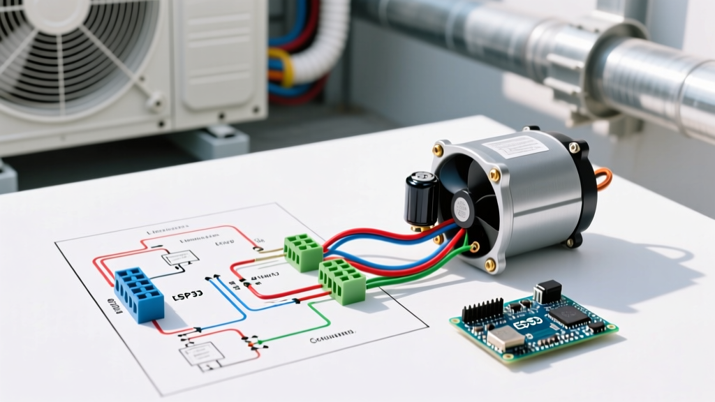
The standard 4-wire PSC condenser fan motor schematic relies on a specific color-code matrix to separate the main (run) winding from the start winding. Misinterpreting these colors is the leading cause of warranty denials and motor burnouts.
Standard 4-Wire PSC Color Code Matrix
| Wire Color | Function | Termination Point | Critical Installation Note |
|---|---|---|---|
| Brown | Run Winding (Start) | Capacitor Terminal 'C' (Common) | Must connect to the designated fan capacitor terminal, not the compressor terminal. |
| Brown w/ White Stripe | Start Winding | Capacitor Terminal 'F' (Fan) | CRITICAL: Never wire this to the same terminal as the solid Brown wire. |
| Purple / Black | Main Line 1 (T2) | Contactor T2 (Load Side) | Supplies continuous line voltage when the contactor pulls in. |
| Yellow / Orange | Main Line 2 (T1) | Contactor T1 (Load Side) | Swap with Purple/Black only if motor rotation needs reversing. |
The Golden Rule of Capacitor Wiring: "Brown to C, Brown/White to F." If you wire the Brown/White stripe wire to the 'C' terminal alongside the solid Brown wire, you bypass the capacitor's phase shift. The start winding will remain continuously energized, drawing excessive amperage and tripping the motor's internal thermal overload in under 3 minutes.
Phase 4: Contactor Logic and Line Voltage Routing
According to the U.S. Department of Energy HVAC Guidelines, proper voltage routing ensures the compressor and condenser fan operate synchronously. In a standard single-stage 240V system, the 24V thermostat signal energizes the contactor coil (A1/A2), pulling the contacts closed.
- Line Side (L1/L2): 240VAC enters from the disconnect.
- Load Side (T1/T2): 240VAC exits to the compressor and fan motor.
- Defrost Board Integration: In heat pump systems, the fan motor's Purple/Black wire often routes through the defrost control board's 'FAN' relay rather than directly to T2. This allows the board to interrupt the fan during the defrost cycle while keeping the compressor running to melt ice off the coil.
Wire Gauge Selection & NEC Article 440 Compliance
Motor circuit conductors must be sized at 125% of the rated load current. If your condenser fan motor draws 1.2 Amps, but the compressor draws 18 Amps, the branch circuit is sized for the combined load. For a standard 30-Amp HACR breaker, you must use a minimum of 10 AWG THHN copper wire. If the unit requires a 40-Amp breaker, step up to 8 AWG copper. Using 12 AWG wire on a 30A breaker is a severe fire hazard and an immediate code violation.
Phase 5: Edge Cases & Universal Motor DIP Switches
When OEM parts are backordered, technicians turn to universal motors like the Mars Rescue series. These motors abandon the traditional 4-wire color code in favor of an integrated control module with DIP switches and a 9-pin harness.
- Identify the OEM RPM and HP: Set the DIP switches on the motor housing to match the original nameplate (e.g., 825 RPM, 1/4 HP).
- Capacitor Bypass: Universal ECM/PSC hybrid motors often have the capacitor logic built into the module. Do not wire the old run capacitor to these motors unless the manufacturer's specific wiring diagram for condenser fan motor integration explicitly demands it.
- Rotation Setup: Universal motors feature a dedicated 'Reverse' pin or switch. If the fan is blowing air upward but pulling debris downward (or vice versa), simply toggle the rotation switch rather than swapping line voltage wires.
Phase 6: Commissioning and Amp Draw Verification
Once the wiring diagram has been executed and all connections are torqued, commissioning begins. The Air-Conditioning, Heating, and Refrigeration Institute (AHRI) emphasizes that verifying operational amperage is the only way to confirm a successful installation.
- Energize the disconnect and call for cooling at the thermostat.
- Clamp your multimeter around the Purple/Black (T2) wire only. Never clamp around both line wires, as the opposing magnetic fields will cancel out and read zero.
- Compare the running amperage to the nameplate FLA. A 1/4 HP motor drawing 1.4 FLA should read between 1.1 and 1.3 Amps under normal ambient conditions (75°F - 85°F).
- Listen for the 'click' of the contactor and verify the fan blade is rotating counter-clockwise (when viewed from above) to push air upward through the coil.
Troubleshooting Common Failure Modes Post-Installation
Even with a perfect wiring diagram execution, environmental factors can mimic electrical faults. If the motor hums but fails to spin, the capacitor may be weak (test with a multimeter's capacitance setting; it should be within +/- 6% of the rated MFD). If the motor runs for 10 minutes and shuts off, you are likely experiencing thermal overload trip due to restricted coil airflow or an undersized replacement motor struggling against high static pressure. Always clean the condenser coil with a low-pressure foaming cleaner before finalizing the installation to ensure optimal heat rejection and motor longevity.