
Decoding the Wiring Diagram for a Single Phase Motor
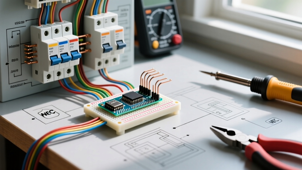
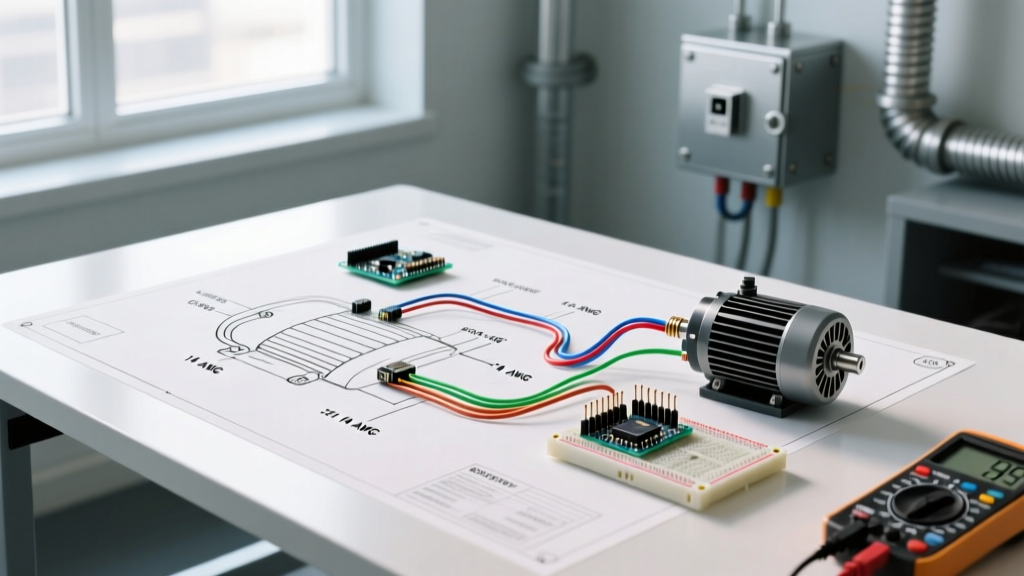
When installing or troubleshooting industrial, agricultural, or heavy residential equipment, understanding the wiring diagram for a single phase motor is only half the battle. While the load-side connections (T1, T2, T3) and capacitor terminals often get the most attention, the supply-side integration—specifically the breaker panel, wire sizing, and disconnect mechanisms—dictates the safety and longevity of the entire system.
Single-phase motors (including capacitor-start, split-phase, and permanent split capacitor designs) are notorious for high inrush currents. If your panel and breaker setup is not engineered to handle the Locked Rotor Amperage (LRA) while still protecting the branch circuit conductors, you will face constant nuisance tripping, voltage drop, or catastrophic wire failure. This guide bridges the gap between the motor's internal schematic and your main electrical panel, ensuring full compliance with the 2026 National Electrical Code (NEC).
The Supply Side: Breaker Sizing and NEC Article 430
The most common mistake DIYers and junior electricians make is sizing the circuit breaker based on the motor's Full Load Amps (FLA). A standard 1 HP, 120V single-phase motor has an FLA of roughly 16 amps. If you install a standard 20A thermal-magnetic breaker, it will likely trip the moment you flip the switch. Why? Because the LRA (inrush current) can spike to 96 amps or more for the first few milliseconds while the rotor overcomes inertia.
To solve this, NFPA 70 (NEC) Article 430.52 provides specific exceptions for motor circuits. It allows the use of inverse-time circuit breakers rated up to 250% of the motor's FLA to accommodate startup surges without tripping.
Motor Sizing & Breaker Matrix (Single-Phase)
The table below outlines the standard requirements for common single-phase motor sizes. Note that wire sizing is governed by NEC 430.22 (125% of FLA), while breaker sizing is governed by NEC 430.52 (up to 250% of FLA).
| Motor HP | Voltage | FLA (Amps) | Min Wire Size (THHN Cu) | Max Inverse-Time Breaker |
|---|---|---|---|---|
| 1/2 HP | 120V | 9.8 A | 14 AWG | 25 A |
| 1 HP | 120V | 16.0 A | 12 AWG | 40 A |
| 1.5 HP | 240V | 10.0 A | 12 AWG | 25 A |
| 3 HP | 240V | 17.0 A | 10 AWG | 45 A |
| 5 HP | 240V | 28.0 A | 8 AWG | 70 A |
Pro Tip: If the calculated maximum breaker size does not correspond to a standard breaker rating (e.g., 45A), the NEC permits you to round up to the next standard size (e.g., 50A), provided the wire is adequately protected by the motor's internal overload device.
Overload Protection vs. Short-Circuit Protection
A critical concept in motor wiring is separating short-circuit protection from overload protection. The circuit breaker in your panel is designed exclusively for short-circuit and ground-fault protection. It is not designed to protect the motor from burning out if it is mechanically overloaded.
According to NEMA MG 1 standards, single-phase motors must be equipped with separate overload protection. This is typically achieved via:
- Internal Thermal Protectors: A bimetallic switch embedded in the motor windings that opens the circuit if temperatures exceed safe limits. These can be auto-reset (common in HVAC fans) or manual-reset (required for compressors and saws to prevent unexpected restarts).
- External Overload Relays: Used in conjunction with magnetic motor starters. The relay monitors the current draw and drops out the contactor coil if the FLA is exceeded for a sustained period.
Step-by-Step Panel Termination & Torque Specs
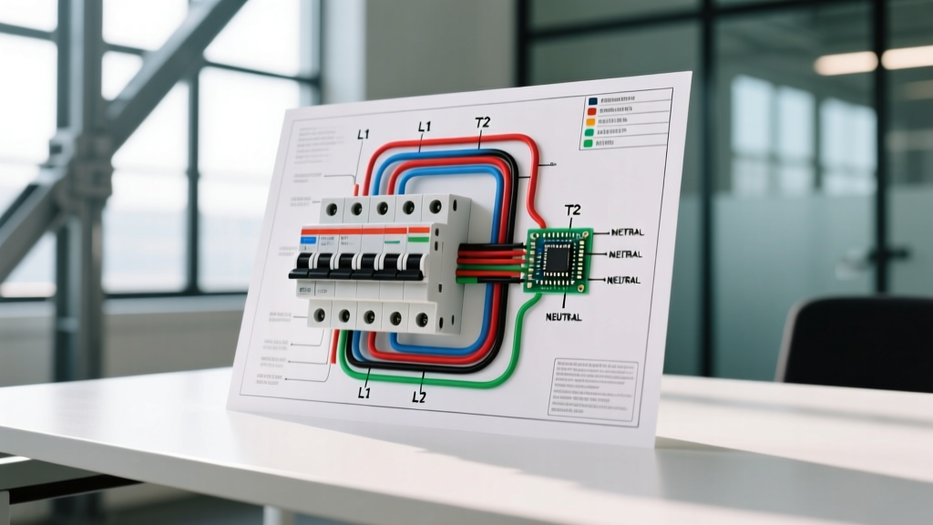
When routing the motor circuit back to the breaker panel, precision matters. Loose connections cause arcing, voltage drop, and thermal imaging hotspots. Follow these exact steps for terminating a 240V single-phase motor circuit using a standard double-pole breaker (e.g., Square D HOM230 or Siemens Q230):
- De-energize and Verify: Turn off the main breaker. Use a non-contact voltage tester and a CAT III multimeter to verify zero voltage on the bus bars.
- Strip the Conductors: Strip exactly 5/8-inch of insulation from 14-10 AWG THHN wires, or 3/4-inch for 8-2 AWG. Do not nick the copper.
- Land the Hots: Insert the black and red (or white re-identified with phase tape) conductors into the double-pole breaker terminals.
- Apply Precise Torque: Using an insulated torque screwdriver, tighten the terminal screws to the manufacturer's specification. For most Square D Homeline and Siemens breakers, this is 20 to 25 in-lbs. Under-torquing leads to thermal failure; over-torquing strips the threads.
- Neutral and Ground: If your wiring diagram for a single phase motor requires a 120V control circuit (e.g., for a contactor coil or timer), land the white neutral on the neutral bus bar and the bare/green ground on the grounding bus bar. Never mix neutrals and grounds on a subpanel.
Control Circuits: Contactors and Magnetic Starters
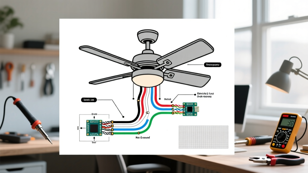
For motors larger than 2 HP, or those requiring remote switching (like a pressure switch on a well pump), the wiring diagram for a single phase motor will include a magnetic contactor. The high-amperage 240V power flows through the contactor's main lugs (L1/L2 to T1/T2), while a low-amperage 120V control circuit operates the coil.
Wiring the Coil (A1 & A2): Route a 120V supply from a dedicated breaker to the pressure switch or control relay. From the switch, run a wire to the A1 terminal on the contactor coil. Connect the A2 terminal directly to the neutral bus. When the pressure drops, the switch closes, energizing the 120V coil, which pulls the heavy-duty contacts closed to start the 240V motor.
Troubleshooting Nuisance Tripping & Failure Modes
If your newly wired motor circuit trips the breaker immediately or after a few minutes of runtime, do not simply swap in a larger breaker. Diagnose the root cause using these field-tested methods:
1. The Weak Start Capacitor
Capacitor-start motors rely on an electrolytic capacitor to provide the phase shift needed for starting torque. If the capacitor degrades and drops below 90% of its rated microfarads (µF), the motor will lug, drawing sustained LRA until the breaker trips. Test the capacitor with a multimeter featuring capacitance testing (such as the Fluke 87V). Always discharge the capacitor with a 20k-ohm, 5-watt resistor before testing.
2. Voltage Drop on Long Runs
The U.S. Department of Energy emphasizes that voltage drop severely impacts motor efficiency and heat generation. If your well pump is 250 feet from the panel, 10 AWG wire might be sufficient for ampacity, but it will cause a voltage drop exceeding the recommended 3% limit. The motor will draw higher amps to compensate for the low voltage, eventually tripping the thermal overload. Always calculate voltage drop for runs over 75 feet and upsize the wire accordingly.
3. Mechanical Binding
Disconnect the motor from the load (e.g., remove the drive belt or uncouple the pump). If the motor starts and runs perfectly without the load, your electrical wiring is correct, and the issue is mechanical binding, seized bearings, or a clogged impeller.
Final Safety Directives
Always install a local disconnect switch within sight of the motor, as mandated by NEC Article 430.102. For outdoor or damp locations, ensure all breakers are HACR (Heating, Air Conditioning, and Refrigeration) rated, and use NEMA 3R or 4X enclosures for exterior disconnects. By respecting the distinct roles of branch-circuit protection and motor overload protection, your single-phase motor installations will remain safe, efficient, and code-compliant for decades.