
Decoding the Hampton Bay Ceiling Fan Electrical Wiring Diagram
Hampton Bay is one of the most popular residential ceiling fan brands on the market, serving as a flagship line for The Home Depot. However, because Hampton Bay sources its models from various overseas manufacturers (such as TAL and Air Cool Industrial), the internal wiring configurations and included remote receivers can vary significantly from one model to the next. Understanding the specific Hampton Bay ceiling fan electrical wiring diagram for your setup is critical to avoiding blown RF receivers, humming motors, or dangerous electrical faults.
Whether you are installing a basic 52-inch flush-mount fan or a 60-inch smart-enabled model with a DC motor, the fundamental principles of line voltage, switch legs, and neutral returns remain the same. This guide breaks down the exact wire color codes, receiver integration steps, and National Electrical Code (NEC) requirements you need to know for a safe, code-compliant installation in 2026.
Core Wire Color Mapping: Fan to House Wiring
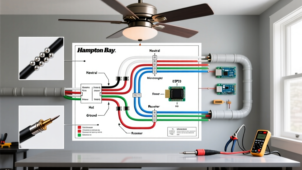
Before touching any wire nuts, you must identify the conductors coming from your ceiling junction box and match them to the fan's lead wires. Most standard Hampton Bay AC motor fans utilize a universal color-coding system. Below is the definitive reference table for direct-wire installations (bypassing remote receivers).
| Fan Wire Color | House Wire Color | Function & Description |
|---|---|---|
| Black | Black (or Red) | Fan Motor Hot: Provides switched line voltage (120V) to the fan motor. |
| Blue | Red (or Black) | Light Kit Hot: Provides switched line voltage to the integrated LED module or light fixture. |
| White | White | Neutral Return: Completes the 120V AC circuit. Must never be connected to a ground or hot wire. |
| Green / Bare Copper | Bare Copper / Green | Equipment Ground: Safety path for fault currents. Mandatory per NEC Article 250. |
The Dual-Switch Scenario (Independent Control)
If your ceiling box has both a Black (hot) and a Red (switched hot) wire, your wall features two separate switches. In this scenario, connect the Fan Black to the House Black, and the Fan Blue to the House Red. This allows you to control the fan motor and the light kit independently from the wall. If you only have a single Black hot wire in the ceiling, you must connect both the Fan Black and Fan Blue to the single House Black wire, relying on the fan's pull chains or remote control to toggle the light and motor separately.
Integrating the Hampton Bay RF Remote Receiver
Many modern Hampton Bay fans include a radio-frequency (RF) remote control system. The most common receiver models packed in the box are the UC7080T, MR101TX, or the newer CHQ9096T. When using a receiver, the standard wiring diagram changes completely. The receiver acts as a middleman between your house wiring and the fan wiring.
Step-by-Step Receiver Wiring Sequence
- Identify the Receiver Inputs: The receiver will have an 'AC IN' side with a Black, White, and sometimes Green wire.
- Connect House to Receiver: Connect the House Black (Hot) to the Receiver Black (AC IN L). Connect the House White (Neutral) to the Receiver White (AC IN N). Connect the House Ground to the Fan Canopy Ground.
- Connect Receiver to Fan: On the 'Output' side, match the Receiver Black to the Fan Black (Motor), Receiver Blue to the Fan Blue (Light), and Receiver White to the Fan White (Neutral).
- Set the DIP Switches: Before closing the canopy, ensure the 4-position DIP switches on the receiver perfectly match the DIP switches inside the battery compartment of the handheld remote. If they do not match, the fan will not respond to commands.
CRITICAL WARNING: Never swap the Line (Hot) and Neutral wires on the AC IN side of a Hampton Bay RF receiver. While AC current alternates, the internal DC rectifier circuit on these specific receiver boards is polarity-sensitive. Reversing them will instantly blow the internal fuse or fry the RF microcontroller, rendering the remote useless and requiring a $25-$40 replacement unit.
Common Failure Modes and Troubleshooting
Even with a perfect wiring diagram execution, Hampton Bay fans can develop specific electrical faults over time. Understanding these edge cases will save you from unnecessarily replacing the entire motor assembly.
1. The Motor Hums but Will Not Spin
If your fan receives power (you hear a distinct 60Hz hum from the motor housing) but the blades do not turn, the issue is rarely the wiring diagram itself. Instead, the run capacitor has failed. Hampton Bay AC motors typically utilize a dual or single run capacitor rated between 1.5µF and 4.5µF at 250V AC. Over time, the dielectric fluid inside the capacitor degrades due to heat trapped in the canopy. Replacing this $6 component (usually housed in a small black rectangular plastic block inside the switch cup) resolves the issue 95% of the time.
2. Light Kit Flickers or Buzzes on Dimmer Switches
If you wired the Blue wire to a wall dimmer, you may experience severe flickering or an audible buzzing from the light kit. Most standard Hampton Bay LED modules are not compatible with legacy incandescent dimmers. You must either use a standard toggle switch or upgrade to a CFL/LED-rated dimmer (such as the Lutron Diva DVCL-153P). If your fan uses a remote receiver, never wire the receiver to a wall dimmer; the chopped sine wave from the dimmer will destroy the receiver's logic board.
NEC Compliance and Mounting Safety Standards
Proper wiring is only half the battle; structural and code compliance is equally vital. According to the National Fire Protection Association (NFPA), which publishes the NEC, ceiling fans must be supported by boxes specifically listed for fan support.
- NEC Article 314.27(C): Requires that ceiling fans weighing more than 35 pounds be supported by an outlet box specifically listed and marked for fan support. While many standard 52-inch Hampton Bay fans weigh between 20 and 28 pounds, larger 60-inch wood-blade models and commercial-grade variants easily exceed the 35-pound threshold.
- UL 507 Standard: Ensure your mounting bracket utilizes the provided lag screws directly into the structural joist, or use a UL-listed fan-rated brace box if mounting between joists.
- Wire Gauge Verification: Most residential fan circuits are protected by a 15A or 20A breaker. Ensure your house wiring is 14 AWG (for 15A) or 12 AWG (for 20A). The fan's internal lead wires are typically 18 AWG, which is permissible under UL standards for appliance leads, but you must use proper wire nuts (usually the small orange or yellow wire nuts provided) to bridge the gauge gap securely.
For broader energy efficiency guidelines and safety tips regarding ceiling fan usage and airflow optimization, the U.S. Department of Energy provides excellent resources on maximizing seasonal downdraft and updraft settings to reduce HVAC loads.
Frequently Asked Questions (FAQ)
Can I wire a Hampton Bay fan without a ground wire?
No. The Electrical Safety Foundation International (ESFI) strongly advises against operating any permanently installed motorized appliance without an equipment ground. If your older home lacks a ground wire in the ceiling box, you must either retrofit a ground wire, replace the box with a properly grounded metal conduit system, or install a GFCI breaker at the panel (though the latter does not replace the need for a physical ground for surge protection).
Why does my Hampton Bay fan have a yellow wire?
On select newer DC-motor Hampton Bay models, a yellow wire may be present. This is typically a data or communication wire used for smart-home integration (like Wi-Fi or Bluetooth modules) or specific multi-speed control boards. Never connect a yellow data wire to a 120V AC hot source, as it will instantly destroy the smart module.
How do I bypass the remote receiver if it breaks?
If your UC7080T receiver fails and you want to convert the fan to standard pull-chain operation, simply remove the receiver from the canopy. Connect the House Black directly to both the Fan Black and Fan Blue wires using a wire nut. Connect House White to Fan White, and House Ground to Fan Ground. You will lose remote functionality, but the fan and light will operate via their physical pull chains.