
Why Your 4x4 Needs a Dedicated Dual Battery Switch
In overland and expedition 4x4 builds, managing DC power is not a luxury; it is a survival requirement. A dedicated dual battery system ensures that your auxiliary loads—such as 12V compressor fridges, camp lighting, and ham radios—never deplete your primary cranking battery. While automatic voltage-sensitive relays (VSRs) are popular, a manual rotary switch remains the gold standard for absolute driver control, especially in harsh environments where parasitic draws can silently kill a battery overnight. Understanding the correct wiring diagram for dual battery switch configurations is critical to prevent alternator damage, mitigate fire risks, and ensure reliable engine starts after days off-grid.
Core Components & Sizing Specifications
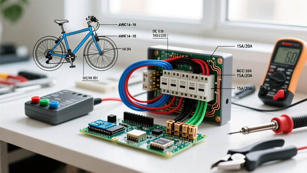
Undersized cables and inadequate overcurrent protection are the leading causes of DC electrical fires in modified vehicles. The following bill of materials reflects a robust, expedition-grade setup designed to handle high-amperage starter surges and continuous auxiliary loads.
| Component | Specification / Model | Estimated Cost (2026) | Purpose |
|---|---|---|---|
| Manual Switch | Blue Sea Systems 9001e e-Series | $68.00 | Primary battery isolation and parallel linking |
| Main Cable | 1/0 AWG Temco Welding Cable | $3.80 / ft | Low voltage drop for high-cranking amps |
| Overcurrent Protection | Class T 250A Fuse & Block | $45.00 | 20,000 AIC short-circuit protection |
| Terminals | 3/8" Marine Heat Shrink Ring | $1.50 / ea | Corrosion-resistant mechanical connections |
| Crimping Tool | Hydraulic Crimper (6-50mm²) | $85.00 | Gas-tight crimps on 1/0 AWG lugs |
Manual vs. Automatic: Choosing the Right Isolation Method
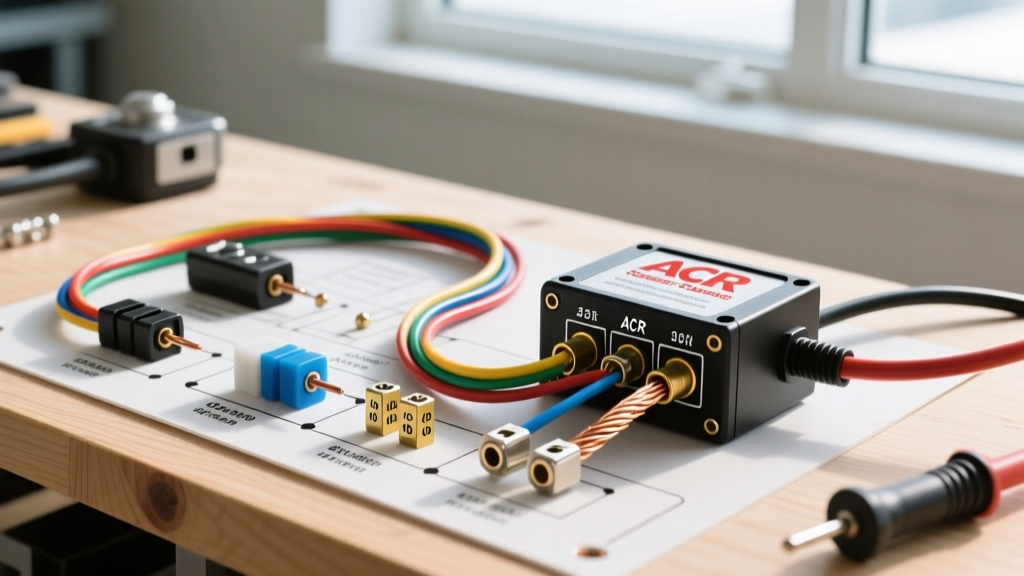
Before executing the wiring diagram for dual battery switch routing, it is vital to understand how manual switches compare to automatic charging relays (ACRs) in real-world 4x4 scenarios.
| Feature | Manual Rotary Switch (1/2/Both/Off) | Automatic VSR / ACR |
|---|---|---|
| Driver Control | Absolute; requires manual intervention | Automated; voltage-sensing |
| Parasitic Draw | Zero (when switched to Off or 1) | Low (10mA - 30mA for relay coil) |
| Winch Paralleling | Requires heavy-duty bypass solenoid | Often fails to trigger under winch load |
| Failure Mode | Mechanical contact wear over years | Electronics/sensor failure in dust/water |
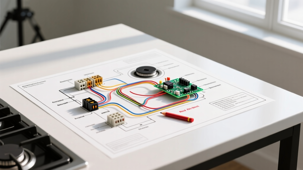
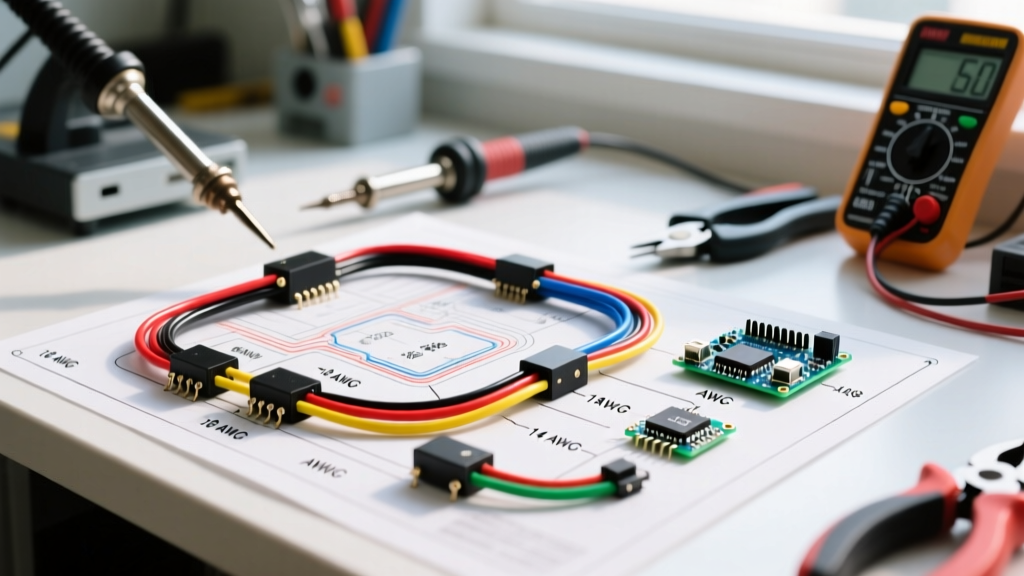
Step-by-Step Wiring Diagram for Dual Battery Switch
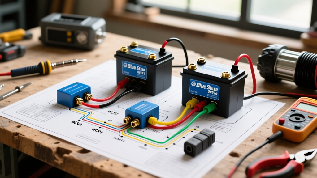
The following procedure details the routing for a Blue Sea 9001e e-Series switch. This configuration isolates the house bank while allowing the alternator to charge both batteries when switched to "Both" or "1".
1. Battery to Switch Routing
Run 1/0 AWG cable from the positive post of Battery 1 (Cranking) to a Class T fuse block mounted within 7 inches of the battery terminal, as mandated by ABYC E-11 DC wiring standards. From the fuse, route the cable to Terminal "1" on the rotary switch. Repeat this exact process for Battery 2 (House), routing through its own Class T fuse to Terminal "2" on the switch. Using individual Class T fuses for each battery is critical; lithium or large AGM banks can dump thousands of amps during a dead short, and standard ANL fuses lack the Ampere Interrupting Capacity (AIC) to safely extinguish the arc.
2. Switch Common to Distribution
The "Common" terminal on the switch is your main output. Run a 1/0 AWG cable from the Common terminal to your main positive distribution busbar. This busbar will feed your starter solenoid, main fuse panel, and auxiliary relay blocks. Never wire the alternator output directly to the switch; always route it to the main busbar or starter solenoid.
3. Grounding Architecture
Do not rely on the vehicle chassis for high-amperage dual battery grounds. Run 1/0 AWG ground cables from both battery negative posts to a dedicated negative busbar, and from there to the engine block and chassis. Coat all ground contact points with dielectric grease after sanding to bare metal to prevent galvanic corrosion.
Integrating the High-Amperage Winch Bypass
A common edge case in 4x4 builds is winching. A heavy-duty winch can pull 400A+ under stall load. While switching the manual rotary switch to "Both" theoretically parallels the batteries, the internal contacts of the switch are not designed to sustain 400A without significant voltage drop and heat generation. To solve this, integrate a continuous-duty solenoid (such as the Cole Hersee 24063) wired directly between the positive posts of both batteries. Wire a momentary dash switch to trigger the solenoid coil. When winching, hold the dash switch to physically parallel the batteries at the posts, bypassing the rotary switch entirely and preventing internal contact welding.
Critical Edge Cases & Alternator Protection
The most catastrophic failure mode when using a manual wiring diagram for dual battery switch setups is switching the rotary knob to "Off" while the engine is running. This instantly severs the alternator's load path, causing a massive voltage spike that will blow the alternator's internal rectifier diode pack within milliseconds. To prevent this, install an Alternator Protection Device (APD) wired to the alternator's ignition sense wire, or implement strict operational discipline: never touch the switch while the key is in the "On" position. Furthermore, refer to NFPA 70 (NEC) guidelines regarding overcurrent protection to ensure your DC fusing aligns with modern safety baselines.
ABYC & NFPA Compliance for DC Routing
When routing 1/0 AWG cables through the vehicle firewall or chassis, physical protection is non-negotiable. Use heavy-duty rubber grommets for every bulkhead pass-through. Secure cables every 18 inches using UV-resistant adhesive-lined cable clamps. Avoid zip-ties for primary battery cables, as vibration will cause the nylon to fatigue and snap, allowing the heavy cable to chafe against the chassis and create a dead short. For comprehensive hardware options and installation diagrams, consulting manufacturer resources like Blue Sea Systems Battery Switches provides excellent visual references for terminal clearances.
Troubleshooting Voltage Drop & Parasitic Draws
After completing the installation, validate your work with a digital multimeter. Set the meter to DC millivolts (mV). Place the red probe on the battery positive post and the black probe on the corresponding switch terminal. Have an assistant crank the engine. A healthy, properly crimped 1/0 AWG connection should show less than 10mV of drop. If you read 30mV or higher, you have a high-resistance joint—likely caused by an incomplete crimp or stranded wire fraying inside the heat shrink. Cut, strip, and re-crimp the terminal immediately. To test for parasitic draws, switch the system to "1" (cranking battery isolated), disconnect the negative terminal, and place the multimeter in series (Amps mode). A healthy isolated cranking battery should show a draw of less than 50mA (accounting for the ECU memory).
Frequently Asked Questions
Can I use 4 AWG wire instead of 1/0 AWG for the battery switch?
No. 4 AWG wire is rated for roughly 60A continuous. A 4x4 diesel or large-displacement gas engine can pull 250A to 400A during cranking. Using 4 AWG will result in severe voltage drop, slow cranking speeds, and melted insulation.
Do I need a battery isolator if I have a manual switch?
How do I wire solar panels into this manual switch setup?
Wire the solar charge controller directly to the House Battery (Battery 2) positive and negative busbars, completely independent of the manual switch. This ensures your solar panels will always maintain the house bank, even if the switch is left in the "Off" or "1" position.