
The Critical Role of the Wiring Diagram in Motor Diagnostics
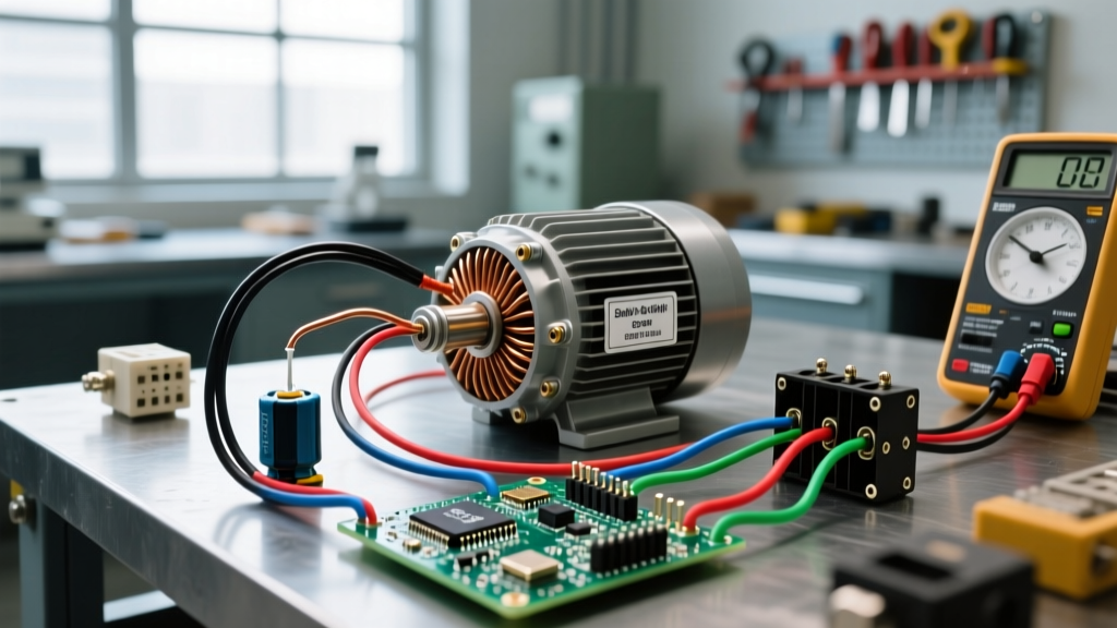
When a single-phase induction motor fails to start, hums loudly, or trips a breaker, guessing the root cause is a waste of time and money. Whether you are working on a 1/2 HP HVAC blower or a 5 HP Leeson Farm Duty compressor motor, the manufacturer's schematic is your primary diagnostic map. Troubleshooting with an electric motor wiring diagram single phase allows you to isolate the exact sub-circuit—be it the start winding, run winding, centrifugal switch, or capacitor bank—before you ever unscrew a terminal lug.
In 2026, with replacement costs for premium efficiency motors (like the Baldor-Reliance Super-E series) ranging from $250 to over $600, accurately diagnosing a $20 faulty start capacitor versus a burnt-out winding saves significant capital. This guide leverages National Electrical Manufacturers Association (NEMA) standards to teach you how to read, interpret, and actively troubleshoot single-phase motor schematics using a digital multimeter.
Decoding the Schematic: NEMA Terminal Designations
Before probing with a multimeter, you must understand the standardized language of the diagram. According to the NEMA MG 1 standard for motors and generators, single-phase dual-voltage motors utilize specific alphanumeric terminal markings to dictate winding configurations. Misinterpreting these on the wiring diagram is the leading cause of catastrophic failure when converting between 115V and 230V operations.
Standard Terminal Identifiers
- T1, T2, T3, T4: These designate the main (run) windings. On a dual-voltage motor, the diagram will show these connected in parallel for low voltage (115V) and in series for high voltage (230V).
- T5, T8: These designate the auxiliary (start) windings. The start winding is only in the circuit during the acceleration phase.
- T6, T7: Often reserved for thermal overload protectors or thermostat leads embedded in the stator slots.
Pro-Tip: Never assume wire color codes match the schematic perfectly on older or refurbished motors. Always trace the physical wires to the terminal board and verify against the diagram printed on the motor's nameplate or inside the peckerhead (connection box) cover.
Diagnostic Matrix: Symptoms vs. Diagram Checkpoints
Use this troubleshooting matrix to map physical symptoms directly to specific checkpoints on your electric motor wiring diagram single phase. This structured approach eliminates guesswork and prevents unnecessary part replacements.
| Observed Symptom | Diagram Checkpoint | Expected Multimeter Reading | Probable Fault & Action |
|---|---|---|---|
| Motor hums, shaft will not turn (manual spin starts it) | Start Winding (T5-T8) & Centrifugal Switch | Continuity through switch; 10-25 ohms across start coil | Open start circuit. Clean centrifugal contacts or replace start capacitor ($15-$30). |
| Motor starts but overheats and trips overload quickly | Run Capacitor (PSC Motors) or Run Winding | Capacitance within ±5% of µF rating; 2-5 ohms on run coil | Weak run capacitor or shorted run winding turns. Test capacitor with Fluke meter. |
| Breaker trips instantly upon energizing | Main Power Input (L1/L2) to Ground | OL (Open Loop) to ground; 0 ohms indicates dead short | Stator ground fault. Motor is unrepairable economically; replace unit. |
| Motor runs in reverse direction | Start Winding Polarity (T5 & T8) | N/A (Wiring configuration error) | Swap T5 and T8 leads as per the reversal schematic on the nameplate. |
Step-by-Step Multimeter Troubleshooting Workflow
To effectively troubleshoot using the diagram, follow this precise field procedure. You will need a high-quality True-RMS multimeter (such as a Fluke 87V or 117) and a dedicated capacitor tester if your meter lacks a microfarad (µF) setting.
Step 1: Lockout/Tagout (LOTO) and Isolation
Safety is non-negotiable. Disconnect all power sources and apply LOTO devices. Use your multimeter in AC Voltage mode to verify zero energy at the motor's line terminals (L1 and L2). Single-phase 230V circuits carry lethal potential, and backfeed from run capacitors can deliver a severe shock even when disconnected.
Step 2: Discharge the Capacitors
Single-phase Capacitor-Start (CSIR) and Capacitor-Start Capacitor-Run (CSCR) motors contain high-energy storage components. Use a 20,000-ohm, 5-watt bleeder resistor across the capacitor terminals for 10 seconds before handling. Never short a capacitor with a screwdriver; this damages the internal foil and the screwdriver tip.
Step 3: Map and Test the Windings
Disconnect the motor leads from the terminal board to isolate the windings from the external circuit. Referring to your wiring diagram, set your multimeter to the lowest Ohms range and zero the leads.
- Run Winding Test: Measure across T1 and T4 (or T2 and T3 depending on the specific schematic). A healthy 1 HP run winding typically reads between 2.0 and 4.5 ohms. A reading of 0 ohms indicates a dead short; an 'OL' reading indicates a broken internal wire.
- Start Winding Test: Measure across T5 and T8. The start winding uses thinner gauge wire with more turns, so its resistance should be roughly 3 to 5 times higher than the run winding (typically 12 to 20 ohms). If the start winding reads open, the motor will only hum.
- Ground Fault Test: Switch the meter to the highest Megohm range. Place one probe on a clean, unpainted spot on the motor casing and the other on T1. Repeat for all terminals. Any reading below 2 Megohms indicates degraded winding insulation, requiring motor replacement or professional rewind.
Step 4: Capacitor Verification
If the windings test perfectly but the motor lacks starting torque, the schematic points to the capacitors. As detailed in Fluke's capacitor testing guidelines, disconnect the capacitor and measure its microfarad rating. A 150 µF start capacitor reading 110 µF has lost its dielectric integrity and must be replaced, even if it shows no physical bulging or leaking.
Edge Cases: Dual Voltage Wiring Mistakes
The most frequent cause of 'new' motor failure in the field is incorrect voltage configuration. A standard 115/230V single-phase motor wiring diagram will show two distinct jumper layouts on the terminal board.
For 230V operation, the diagram dictates that the two run winding halves (T1-T2 and T3-T4) are wired in series. The line voltage is applied across T1 and T4, while T2 and T3 are jumpered together. The start winding (T5-T8) is connected in parallel with one half of the run winding. If a technician mistakenly wires the run windings in parallel for a 230V supply, the motor will draw massive current, instantly vaporizing the start winding and tripping the branch circuit breaker.
According to the U.S. Department of Energy's Motor Systems guide, improper voltage configuration and poor power quality account for a significant percentage of premature motor failures in industrial and agricultural settings. Always verify the supply voltage with a multimeter before setting the motor's internal jumpers to match the diagram.
When to Abandon Troubleshooting and Replace
While the wiring diagram helps you isolate faults, economics dictate the final decision. In 2026, the labor rate for a professional motor rewind shop averages $95 to $135 per hour. Rewinding a single-phase motor under 3 HP is rarely cost-effective. If your diagram troubleshooting reveals a burnt run winding, a melted centrifugal switch assembly that cannot be sourced, or a cracked rotor casting, bypass the repair. Replace it with a modern, high-efficiency equivalent (such as a WEG or Baldor general-purpose model) which will offer better thermal protection and lower operating costs over its lifespan.
By systematically following the electric motor wiring diagram single phase, you transform a chaotic breakdown into a logical, step-by-step diagnostic procedure. Trust the schematic, verify with your meter, and prioritize safety above all else.