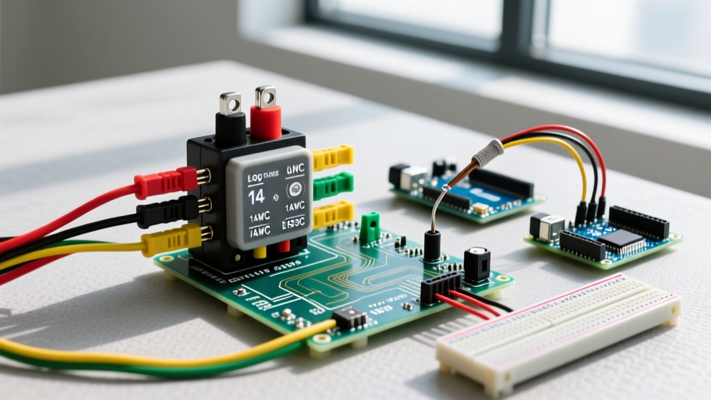

Mastering the Wiring Diagram for Fog Lights: An Automotive Electrical Guide
Upgrading your vehicle with auxiliary lighting is one of the most practical modifications you can make for inclement weather and off-road visibility. However, tapping into a modern vehicle's electrical system requires more than just splicing wires together. A proper wiring diagram for fog lights ensures that your high-draw accessories do not melt factory switches, overload delicate CANBUS modules, or suffer from severe voltage drop. Whether you are installing traditional 55W halogen lamps or the latest generation of high-output LED fog pods, understanding the underlying electrical architecture is critical.
In this comprehensive motor wiring tutorial, we will break down the industry-standard 4-post relay schematic, calculate exact wire gauges based on 2026 LED and halogen power draws, and detail the step-by-step installation process using automotive-grade SAE J1128 wiring standards.
The Core Anatomy: Why You Need a Relay
A common mistake among DIYers is attempting to route the full amperage of the fog lights through the dashboard switch and factory wiring harness. Factory headlight switches are typically rated for minimal current, designed only to trigger a relay or signal a Body Control Module (BCM). Routing 10 to 15 amps directly through a standard toggle switch will cause the internal contacts to arc, overheat, and eventually melt the plastic housing.
The universal wiring diagram for fog lights utilizes a standard ISO 7588 (Bosch-style) 40A automotive relay. This electromechanical switch isolates the high-current "load" circuit from the low-current "trigger" circuit.
Understanding the 4-Post Relay Pinout
- Terminal 30 (Power In): Receives constant 12V+ directly from the battery via an inline fuse.
- Terminal 87 (Power Out): Sends 12V+ to the fog lights when the relay is energized.
- Terminal 86 (Trigger In): Receives a low-current 12V+ signal from your dashboard switch or OEM headlight circuit.
- Terminal 85 (Ground): Completes the trigger circuit by grounding to the vehicle chassis.
Expert Insight: Never use Terminal 87a (the normally closed contact on a 5-post relay) for fog lights. If the relay fails internally or the coil loses ground, 87a could accidentally route power, leaving your lights on and draining your battery overnight. Stick to a strict 4-post SPST (Single Pole, Single Throw) relay for auxiliary lighting.
Wire Gauge and Fuse Sizing Matrix
Selecting the correct wire gauge is dictated by the total amperage draw and the length of the wire run. Voltage drop is the enemy of automotive lighting; a 10-foot run of undersized wire can drop your 13.8V alternator output down to 11.5V at the bulb, drastically reducing lumen output and causing halogen bulbs to burn yellow and dim.
The table below outlines the required specifications based on standard SAE J1128 GXL (Cross-Linked Polyethylene) automotive primary wire, which features superior heat and chemical resistance compared to standard PVC or residential THHN wire.
| Lighting Setup (2026 Standard) | Total Wattage | Max Amperage (at 13.8V) | Recommended Wire Gauge (AWG) | Inline Fuse Size (ATO/ATC) |
|---|---|---|---|---|
| Modern LED Fog Pods (e.g., 3-inch) | 40W (Pair) | 2.9A | 16 AWG | 5A |
| High-Output LED Light Bars (Off-road) | 120W | 8.7A | 14 AWG | 10A |
| Standard Halogen Fog Lights | 110W (55W x 2) | 8.0A | 14 AWG | 10A |
| High-Wattage Halogen / Rally Lights | 200W (100W x 2) | 14.5A | 12 AWG | 15A |
Step-by-Step Fog Light Wiring Tutorial
Follow this precise sequence to ensure a safe, weatherproof, and reliable installation.
Step 1: The Load Circuit (Battery to Relay to Lights)
- Battery Connection: Disconnect the negative battery terminal. Measure and cut a length of 12 AWG or 14 AWG GXL red wire to reach from the battery positive terminal to your chosen relay mounting location.
- Inline Fusing: Install an ATC fuse holder within 6 inches of the battery positive terminal. This is a non-negotiable safety requirement; if the wire chafes against the chassis before the fuse, it will cause a dead short and potentially an electrical fire.
- Relay Termination: Crimp a ring terminal on the battery end and a female spade connector (or Weatherpack terminal) on the relay end. Connect this to Terminal 30.
- Output to Lights: Run a wire from Terminal 87 to the positive inputs of your fog lights. Use adhesive-lined dual-wall heat shrink tubing on all splices to prevent moisture ingress and corrosion.
Step 2: The Grounding Strategy
A poor ground is responsible for 90% of automotive lighting failures. Do not simply wrap a wire around a random bolt. Locate a dedicated, unpainted chassis ground point near the fog lights. Sand away any powder coating or rust, attach a heavy-duty ring terminal, and secure it with a stainless steel bolt and star washer to bite into the bare metal. Apply a dab of dielectric grease over the terminal to prevent galvanic corrosion.
Step 3: The Trigger Circuit (Switch Integration)
The trigger circuit requires significantly less current, so 18 AWG wire is perfectly adequate here.
- Run a wire from your dashboard toggle switch to Terminal 86 on the relay.
- Connect the other side of the toggle switch to an ignition-switched 12V+ source (such as the ACC fuse in the interior fuse box using an add-a-circuit fuse tap). This ensures your fog lights cannot be left on when the vehicle is parked.
- Ground Terminal 85 to a clean chassis point near the relay.
Modern CANBUS and LED Interference Challenges
As of 2026, the vast majority of new vehicles utilize multiplexed CANBUS systems and Pulse Width Modulation (PWM) to control factory lighting. If you attempt to use your factory headlight wiring as the "trigger" source for Terminal 86, you may encounter issues. PWM rapidly pulses the voltage to dim or monitor the bulbs, which can cause your fog light relay to rapidly click or "chatter," ultimately destroying the relay coil and causing the lights to flicker.
The Solution: If tapping into a PWM-controlled headlight wire for your trigger signal, you must install a 12V DC timer delay relay or a dedicated CANBUS decoder module between the factory wire and Terminal 86. This smooths the pulsed signal into a steady 12V+ stream, ensuring your fog light relay engages cleanly.
Troubleshooting Matrix: Common Failure Modes
Even with a flawless wiring diagram for fog lights, environmental factors and minor errors can cause issues. Use this diagnostic matrix to isolate the problem.
| Symptom | Probable Cause | Diagnostic Fix |
|---|---|---|
| Relay clicks, but lights remain off. | Blown main fuse, or severe voltage drop on the load circuit (Terminal 87). | Check the inline fuse near the battery. Use a multimeter to test for 12V+ at the fog light positive connector while the relay is engaged. |
| Lights are dim and flicker with engine RPM. | Bad chassis ground or undersized wire gauge causing resistance. | Perform a voltage drop test across the ground wire. It should read less than 0.1V. Clean and re-terminate the ground. |
| Relay does not click; switch does nothing. | No trigger signal reaching Terminal 86, or blown ACC fuse tap. | Probe Terminal 86 with a test light while the switch is ON. If no power, check the add-a-circuit fuse tap in the interior cabin. |
| Lights stay on after the ignition is turned off. | Trigger wire is connected to a constant 12V+ source instead of an ignition-switched ACC source. | Reroute the switch power feed to a verified key-switched fuse circuit. |
Legal Compliance and Mounting Standards
When installing auxiliary lighting, adherence to federal safety standards is not just a legal requirement; it ensures you do not blind oncoming traffic. According to the Federal Motor Vehicle Safety Standards (FMVSS 108), which governs all automotive lighting equipment in the United States, fog lamps must be mounted on the front of the vehicle at a height between 4 inches and 36 inches above the road surface Code of Federal Regulations - FMVSS 108.
Furthermore, the National Highway Traffic Safety Administration (NHTSA) mandates that fog lights must be aimed downward and slightly outward to illuminate the edges of the roadway without reflecting glare off precipitation back into the driver's eyes. Always ensure your aftermarket housings carry a proper SAE J583 marking, indicating they have been photometrically tested and certified for use as fog lamps on public roads.
Final Thoughts on Automotive Wiring Integrity
Executing a proper wiring diagram for fog lights separates a professional-grade installation from a hazardous hack-job. By utilizing SAE-rated GXL wire, adhesive-lined heat shrink, weatherproof relay connectors, and strict adherence to fuse placement rules, you guarantee that your auxiliary lighting will perform reliably in the harshest conditions. Always prioritize the integrity of the load circuit, respect the limitations of modern CANBUS trigger systems, and verify your mounting heights against federal regulations before taking your vehicle onto public roads.