
Mastering the 3 Phase Electric Motor Starter Wiring Diagram
Wiring a three-phase induction motor requires a precise understanding of both power and control circuits. Whether you are commissioning a 5HP air compressor or a 50HP industrial conveyor belt, the Direct-On-Line (DOL) starter remains the most ubiquitous and cost-effective solution in 2026. This comprehensive tutorial breaks down the 3 phase electric motor starter wiring diagram into actionable steps, ensuring compliance with the latest NFPA 70 National Electrical Code (NEC) standards, specifically Article 430 regarding motors, motor circuits, and controllers.
Unlike single-phase motors that require capacitors to generate a rotating magnetic field, 3-phase motors are self-starting. However, their massive inrush current—typically 600% to 800% of the Full Load Amps (FLA)—demands robust switching and protection mechanisms. Below, we dissect the anatomy of a standard electromechanical DOL starter, providing exact terminal designations, wire sizing data, and advanced troubleshooting protocols.
Core Components of a 3-Phase DOL Starter
Before touching a wire stripper, you must verify your bill of materials. A standard IEC-rated DOL starter assembly consists of four primary components. Pricing reflects average 2026 industrial supply costs:
- Molded Case Circuit Breaker (MCCB) or Fuses: Provides short-circuit and disconnect protection. (e.g., Eaton C-Frame 30A MCCB, ~$140).
- 3-Pole Contactor: The electromagnetic switch that routes power to the motor. (e.g., Schneider Electric TeSys D LC1D18, rated for 18A / 7.5HP at 230V, ~$65).
- Thermal Overload Relay: Protects the motor from sustained overcurrent and phase loss. (e.g., TeSys LRD16, adjustable 9A-13A, ~$55).
- Control Circuit Components: Momentary pushbuttons (Start/Stop), auxiliary contacts, and control fuses.
Anatomy of the Wiring Diagram: Power vs. Control
Every 3 phase electric motor starter wiring diagram is divided into two distinct logical sections: the Power Circuit and the Control Circuit. Mixing these up is the leading cause of catastrophic failure and damaged coils.
1. The Power Circuit (High Current)
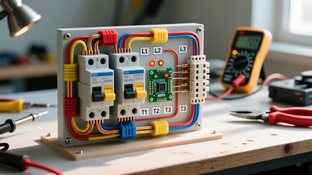
The power circuit carries the heavy 3-phase load from the main supply to the motor terminals. It flows sequentially through the disconnect, the contactor's main poles, and the overload relay's bimetallic heating elements.
- Supply to MCCB: Connect the 3-phase incoming lines (L1, L2, L3) to the top terminals of the MCCB.
- MCCB to Contactor: Run three conductors from the bottom of the MCCB to the top main terminals of the contactor, universally labeled 1L1, 3L2, and 5L3.
- Contactor to Overload: Connect the bottom main terminals of the contactor (2T1, 4T2, 6T3) directly to the top input terminals of the thermal overload relay.
- Overload to Motor: Wire the bottom output terminals of the overload relay (T1, T2, T3) to the motor's terminal box (U, V, W). Ensure the motor nameplate matches the voltage configuration (Star/Wye or Delta) before tightening to the manufacturer's specified torque (typically 1.5 to 2.5 Nm for small frame contactors).
2. The Control Circuit (Low Current Logic)
The control circuit dictates when the contactor pulls in. It is typically powered by a single-phase step-down transformer (e.g., 480V primary to 120V secondary) to protect the operator from high voltage at the pushbuttons.
- Stop Button (NC): Wired in series. Uses Normally Closed contacts to break the circuit when pressed.
- Start Button (NO): Wired in series after the Stop button. Uses Normally Open contacts to complete the circuit when pressed.
- Overload Relay NC Contact (95-96): Wired in series with the Stop button. If the motor overheats, the relay trips this contact, cutting power to the coil.
- Contactor Coil (A1-A2): The electromagnetic load. A1 connects to the Start button; A2 connects to the neutral/return line.
- Auxiliary Seal-In Contact (13 NO - 14 NO): Wired in parallel with the Start button. This is the 'latching' mechanism.
The Latching Logic Explained: When you press the Start button, current flows to A1, energizing the coil. The contactor pulls in, simultaneously closing the main power poles and the 13-14 auxiliary contact. The auxiliary contact bypasses the Start button, 'sealing in' the circuit. When you release the Start button, the coil remains energized via the 13-14 path. Pressing the Stop button breaks the path, de-energizing the coil and dropping out the motor.
Starting Method Comparison Matrix (2026 Standards)
While DOL is standard for smaller motors, larger applications require reduced-voltage starting to prevent grid dips and mechanical shock. Review this matrix to determine if a DOL diagram is appropriate for your specific application.
| Starting Method | Inrush Current | Starting Torque | Relative Cost (2026) | Wiring Complexity |
|---|---|---|---|---|
| Direct-On-Line (DOL) | 600% - 800% FLA | 150% - 200% Full Load | $150 - $300 | Low (Standard 3-wire control) |
| Star-Delta (Wye-Delta) | 200% - 300% FLA | 33% Full Load | $400 - $800 | High (Requires 3 contactors, timer) |
| Solid-State Soft Starter | 250% - 400% FLA | Adjustable / Smooth Ramp | $800 - $2,500+ | Medium (Requires programming, 6 SCR thyristors) |
| Variable Frequency Drive (VFD) | 110% - 150% FLA | Full Torque at Zero Speed | $1,200 - $4,000+ | High (Requires parameter tuning, shielding) |
NEC Wire Sizing and Breaker Selection
Sizing conductors for a 3 phase electric motor starter wiring diagram is not as simple as using standard ampacity tables. According to OSHA Electrical Safety Standards and NEC Article 430.22, motor branch circuit conductors must be sized at 125% of the motor's Full Load Current (FLC) as listed in NEC Table 430.250, not the nameplate ampacity.
| Motor HP | Voltage (3-Phase) | NEC Table FLC | Min. Wire Ampacity (125%) | Copper Wire Size (75°C) | Max Inverse Time Breaker |
|---|---|---|---|---|---|
| 5 HP | 230V | 15.2A | 19.0A | 12 AWG | 40A |
| 10 HP | 230V | 28.0A | 35.0A | 8 AWG | 70A |
| 15 HP | 460V | 21.0A | 26.2A | 10 AWG | 50A |
| 25 HP | 460V | 34.0A | 42.5A | 8 AWG | 80A |
| 50 HP | 460V | 65.0A | 81.2A | 3 AWG | 150A |
Note: The maximum breaker size is calculated at 250% of FLC per NEC Table 430.52 to accommodate the massive starting inrush without nuisance tripping. The overload relay, not the breaker, is responsible for protecting the motor from running overcurrent.
Advanced Troubleshooting and Failure Modes
Even with a perfect diagram, environmental factors and mechanical wear can cause failures. Referencing guidelines from the U.S. Department of Energy Motor Systems Basics, here is how to diagnose the three most common DOL starter failures using a digital multimeter (e.g., Fluke 87V).
Failure Mode 1: Contactor Chattering or Humming
Symptom: The contactor vibrates loudly and the motor fails to start or runs erratically.
Root Cause: Voltage drop in the control circuit or debris on the magnetic pole faces. If the coil requires 120V AC but the control wiring is undersized or the connections are loose, the voltage at A1-A2 may drop below the 85% pull-in threshold.
Fix: Measure voltage directly across A1 and A2 while pressing the Start button. If it reads below 102V, upgrade the control wire gauge or tighten terminal screws. Inspect the E-core and I-core laminations for rust or dirt, which prevents a tight magnetic seal.
Failure Mode 2: Nuisance Thermal Tripping
Symptom: The motor runs for 5 to 10 minutes, then the overload relay trips. Resetting the relay yields the same result.
Root Cause: Phase unbalance or improper overload dial setting. A voltage unbalance of just 1% across the three phases can cause a current unbalance of 6% to 10%, leading to rapid stator heating.
Fix: Measure phase-to-phase voltage at the contactor input (1L1-3L2, 3L2-5L3, 1L1-5L3). If the variance exceeds 1%, contact your utility provider. Ensure the overload relay dial is set exactly to the motor's nameplate Service Factor Amps (SFA), not the NEC table FLC.
Failure Mode 3: Contact Welding (Motor Fails to Stop)
Symptom: Pressing the Stop button de-energizes the coil, but the motor continues to run.
Root Cause: Extreme inrush currents or starting under heavy mechanical load have caused arcing, melting the silver-alloy tips on the main power poles and welding them shut.
Fix: DANGER: Immediately kill power at the upstream MCCB. Do not attempt to pry the contacts apart. The contactor must be replaced. To prevent recurrence, upgrade to a contactor with a higher AC-3 utilization category rating or implement a soft starter to limit inrush current.
Final Safety and Commissioning Checklist
Before energizing your 3 phase electric motor starter wiring diagram for the first time, complete this mandatory checklist:
- Verify all power and control connections are torqued to manufacturer specifications.
- Confirm the overload relay class setting (Class 10 for standard, Class 20 for high-inertia loads).
- Perform a 'bump test' (momentarily energize) to verify motor rotation direction. If reversed, swap any two of the three power leads at the contactor output (2T1 and 4T2).
- Measure running amperage on all three phases using a clamp meter to ensure they are balanced and within the motor's nameplate rating.